SsangYong Korando II (1996-2006 year). Manual — part 233

SSAMGYONG MY2002
4A-10 HYDRAULIC BRAKES
KAA4A020
KAA4A030
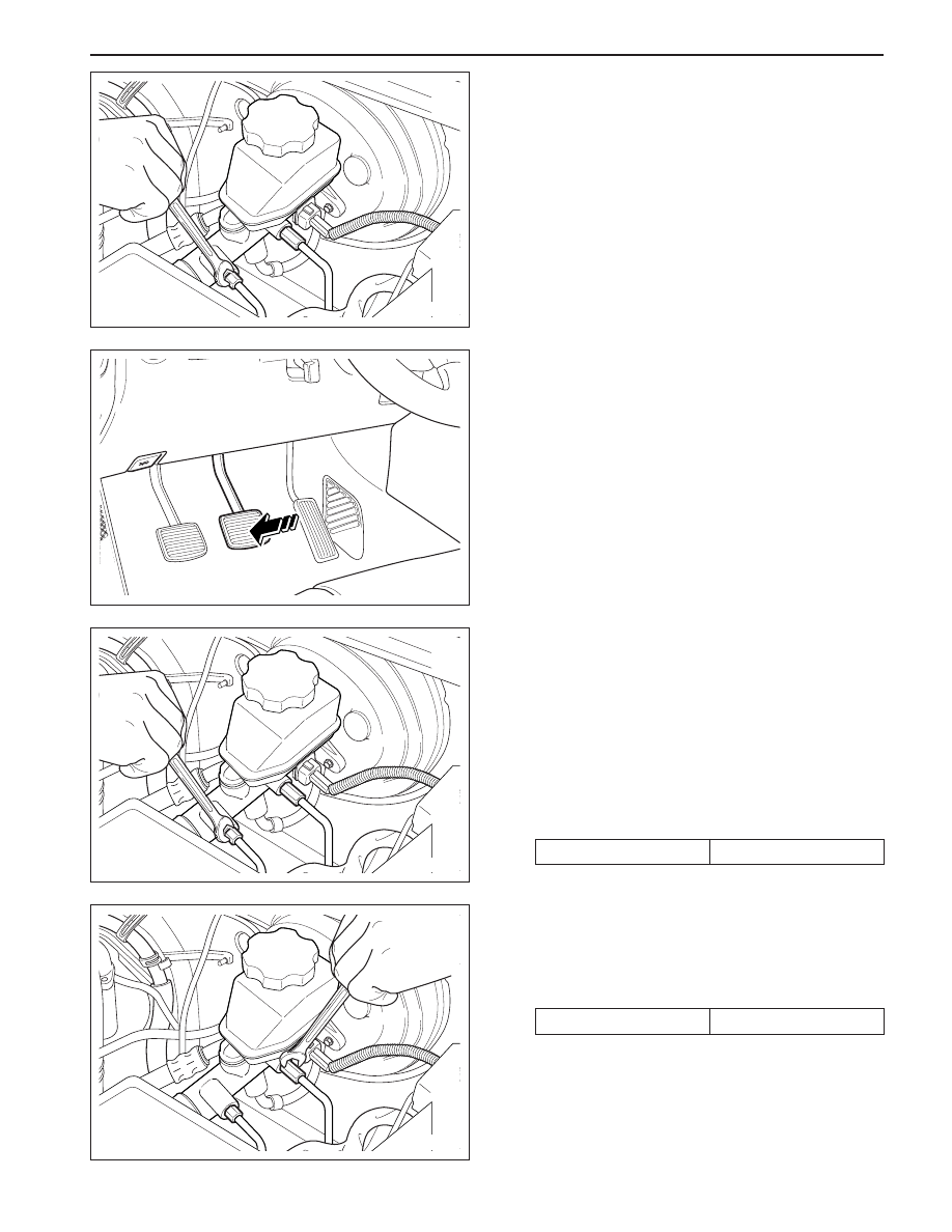
Notice: Keep brake fluid away from painted surfaces
because brake fluid will damage the paint finish.
2. Fill the master cylinder reservoir with brake fluid.
Keep the master cylinder reservoir at least one-
half full during the bleeding operation.
ON-VEHICLE SERVICE
MANUAL BLEEDING THE BRAKES
Removal and Installation Procedure
Important: Manual bleeding of the hydraulic modulator
is not possible. If air enters the antilock brake hydraulic
modulator, or if an unfilled modulator is installed, use
the scan tool to bleed air out of the brake system.
Replacement modulators are shipped already filled
and bled. In normal on-vehicle service procedures
involving the modulator, such as the procedure to
replace the electronic brake control module, air will
not enter the modulator. In such cases, use the
bleeding procedure in this section.
1. Remove the booster reserve by applying the
brakes several times with the engine off, until all
the reserve is depleted.
Important: If no air is suspected to be in the
master cylinder, begin the bleeding procedure at
Step 12. If it is suspected that air is in the master
cylinder bore, then the master cylinder must be
bled, beginning with step 2.
REPAIR INSTRUCTIONS
HYDRAULIC BRAKES 4A-11
SSANGYONG MY2002
KAA4A040
KAA4A020
KAA4A040
KAA4A050
3. Disconnect the brake line at the front of the master
cylinder.
4. Allow the brake fluid to fill the master cylinder until
it begins to flow from the port.
5. Reconnect the brake line at the front of the master
cylinder.
6. Slowly push and hold the brake pedal.
7. While the brake pedal is pushed down, loosen the
brake fitting at the front of the master cylinder to
purge the air from the cylinder.
8. Slightly tighten the brake fitting. Then release the
brake pedal slowly. Wait 15 seconds before continu-
ing with the next step.
9. Repeat Steps 6-8 until all of the air is removed
from the master cylinder bore.
10. Tighten the brake line fitting.
Installation Notice
11. After the air has been bled at the front connection,
bleed the master cylinder at the rear connection
using the same sequence as with the top
connection.
Installation Notice
Tightening Torque
22 N•m (16 lb-ft)
Tightening Torque
17 N•m (13 lb-ft)
SSAMGYONG MY2002
4A-12 HYDRAULIC BRAKES
13. Slowly push and hold the brake pedal. Avoid rapid
pumping of the brake pedal.
14. While the brake pedal is pushed down, loosen the
bleeder valve to purge the air from the caliper.
15. After the air bubbles have escaped into the
container of brake fluid, slightly tighten the rear
bleeder valve.
16. Slowly release the brake pedal. Wait 15 seconds
before proceeding with the next step.
Notice: Keep brake fluid away from painted
surfaces because brake fluid will damage the paint
finish.
17. Repeat Steps 13 - 16 until all of the air is removed.
You will know all of the air is removed when no
bubbles appear in the container when the bleeder
valve is loosened. Keep the master cylinder reser
voir at least one-half full during the bleeding
operation.
18. Tighten the front bleeder valve.
Installation Notice
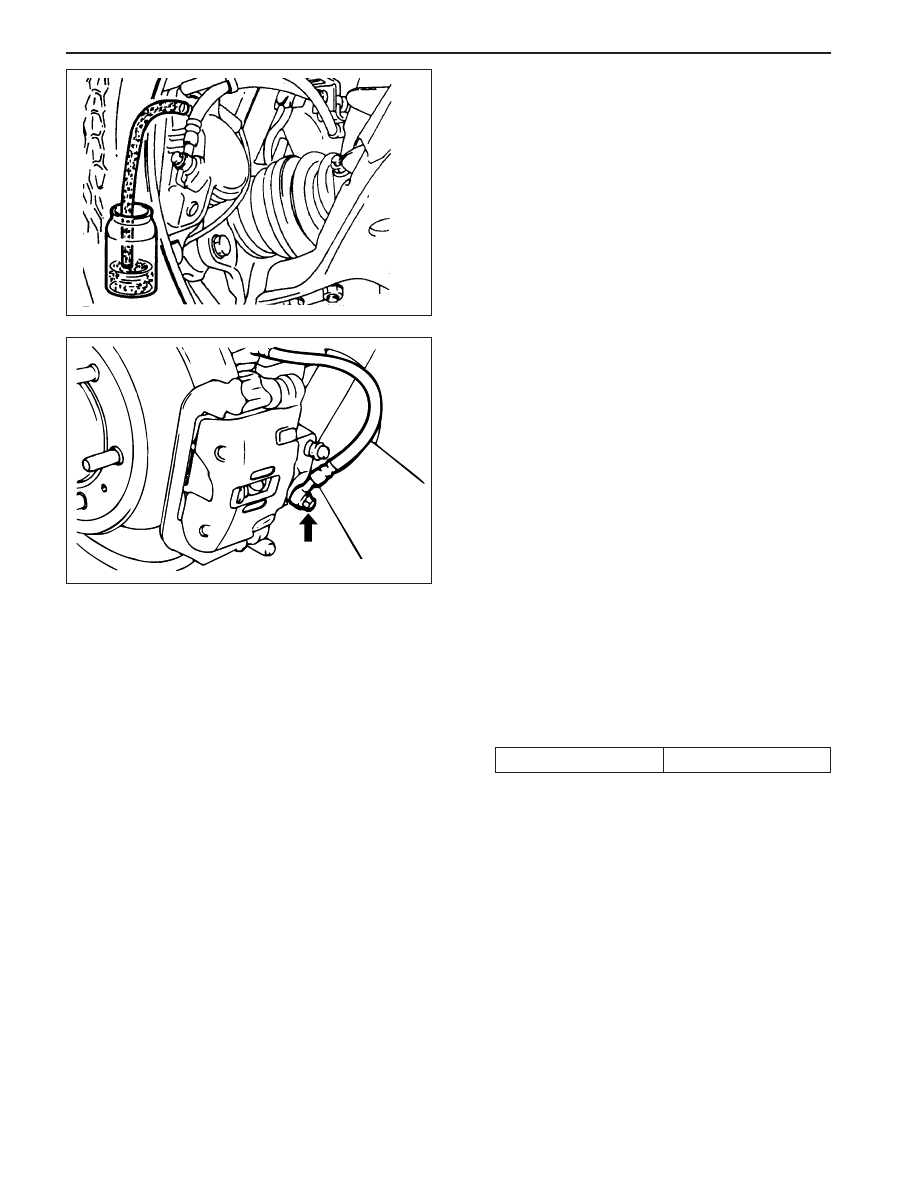
12. Attach a transparent tube over the rear bleeder
valve at the right rear caliper. Allow the tube to
hang submerged in the brake fluid in a transparent
container. (After the right rear caliper is bled in
the following steps, use this procedure at the left
front, the left rear and the right front bleeder valves.)
19. Bleed the remaining calipers in the following order
: left rear, right front, and left front. Use the
procedure in Steps 12 - 17.
20. After all calipers have been bled, check the brake
pedal for sponginess. If the brake pedal is not firm,
repeat the entire bleeding procedure to correct this
condition.
Tightening Torque
10 N•m (89 lb-ft)
KAA4A060
KAA4A070
HYDRAULIC BRAKES 4A-13
SSANGYONG MY2002
Tightening Torque
17 N•m (13 lb-ft)
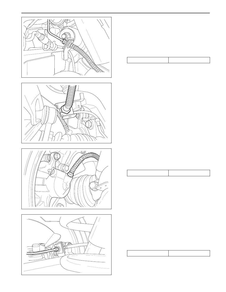
FRONT BRAKE HOSE
Removal and Installation Procedure
1. Raise and suitably support the vehicle.
2. Disconnect the brake line from the brake hose sup
port bracket on the front frame on each side of the
vehicle and remove the retainer.
Installation Notice
KAA4A080
KAA4A090
KAA4A100
KAA4A110
3. Remove the brake hose from the brake hose
support bracket on the upper control arm.
4. Remove the front brake hose-to-front caliper
assembly bolt.
5. Remove the ring seals and the disc brake hose.
Installation Notice
Tightening Torque
30 N•m (22 lb-ft)
•
Bleed the brake system. Refer to “Manual
Bleeding the Brakes” in this section.
•
Check the brake system for leaks.
6. Installation should follow the removal procedure
in the reverse order.
REAR BRAKE HOSE
Removal and Installation Procedure
1. Raise and suitably support the vehicle.
2. Disconnect the brake line from the disc brake hose
at the rear axle bracket on each side of the vehicle.
Installation Notice
Tightening Torque
17 N•m (13 lb-ft)
Нет комментариевНе стесняйтесь поделиться с нами вашим ценным мнением.
Текст