SsangYong Korando II (1996-2006 year). Manual — part 253

ABS AND TCS 4F-27
SSANGYONG MY2002
Step
1
2
3
4
5
6
7
8
9
10
11
12
13
Traction Control System (TCS) Indicator Lamp Inoperative
Action
Go to the chart
for the DTC
Go to “Intermit-
tents and Poor
Connections”
Go to Step 4
Go to Step 5
Go to Step 6
System OK
System OK
Go to Step 10
System OK
Go to Step 11
System OK
Go to Step 14
System OK
Go to Step 2
Go to Step 3
Go to Step 19
Go to Step 8
Go to Step 7
-
-
Go to Step 9
-
Go to Step 12
-
Go to Step 13
-
Value(s)
Install the scan tool and check for any DTCs.
Is any DTC set?
1. Turn the ignition to LOCK.
2. Disconnect the scan tool.
3. Turn the ignition to ON.
4. Observe the EBD indicator lamp.
Does the lamp illuminate for about 2 seconds, then
turn off?
With the ignition still ON, observe the oil pressure
lamp.
Is the oil pressure lamp illuminated?
1. Turn the ignition to LOCK.
2. Disconnect the connector from the EBCM.
3. Connect a jumper from terminal 30 to the grounding
bar in the connector.
4. Turn the ignition to ON.
Does the EBD indicator illuminate?
1. Turn the ignition to LOCK.
2. Examine terminals 19 and 30 at the EBCM connec-
tor on both the ABS wiring harness and on the
EBCM.
Is there a poor connection at any of these terminals?
Repair the faulty terminals or replace the ABS unit, as
required.
Is the repair complete?
Replace the ABS unit.
Is the repair complete?
1. Turn the ignition to LOCK.
2. Disconnect the wire from the negative battery
terminal.
3. Measure the resistance between the negative
battery wire, which is attached to ground, and the
shorting bar in the EBCM connector.
Is the resistance equal to the specified value?
Repair the open or high resistance in the circuit from
EBCM connector, terminal 19 to ground G205.
Is the repair complete?
1. Remove the I/P cluster.
2. Remove and check the TCS indicator bulb.
Is the bulb burned out?
1. Replace the EBD indicator bulb.
2. Replace the I/P cluster.
Is the repair complete?
Check continuity at the I/P cluster connector terminal
D6.
Is the continuity equal to the specified value?
Repair the contact at the I/P cluster connector terminal
D6
Is the repair complate?
-
-
-
-
-
-
-
≈
0
Ω
-
-
-
≈
0
Ω
-
Yes
No

SSANGYONG MY2002
4F-28 ABS AND TCS
Check the wiring harnesses and connectors in circuit
from the I/P cluster terminal D6 to terminal 30 of the
EBCM connector.
Is the voltage equal to the specified value?
Repair the open or high resistance.
Is the repair complete?
Check for continuity between terminal 19 of the ABS
connector and ground G205.
Is the continuity equal to the specified value?
Replace the ABS unit.
Is the repair complete?
Repair the continuity between terminal 19 of the EBCM
connector and ground G205.
Is the repair complete?
1. Turn the ignition to LOCK.
2. Check fuse F30 in the I/P fuse block.
Is fuse F30 blown?
Replace fuse F30.
Is the repair complete?
1. Turn the ignition ON.
2. Check the voltage at fuse F30.
Is the voltage equal to the specifies value?
Repair the power supply to fuse F30.
Is the repair complete?
1. Remove the I/P cluster.
2. Check circuit LR from fuse F30 to terminal A1 of
the I/P cluster connector.
3. Repair any open or high resistance found in a wiring
harness, a splice pack, or a connector.
Is the repair complete?
Step
14
15
16
17
18
19
20
21
22
23
Electronic Brake-Force Distribution System (EBD) Indicator Lamp Inoperative
Action
Go to Step 15
System OK
Go to Step 17
System OK
System OK
Go to Step 20
System OK
Go to Step 22
System OK
System OK
Go to Step 16
-
Go to Step 18
-
-
Go to Step 21
-
Go to Step 23
-
-
∞
-
≈
0
Ω
-
-
-
-
11 - 14v
-
-
Value(s)
Yes
No
ABS AND TCS 4F-29
SSANGYONG MY2002
BLANK
SSANGYONG MY2002
4F-30 ABS AND TCS
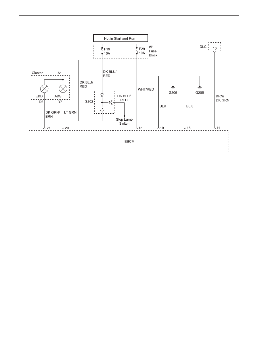
POWER SUPPLY TO CONTROL MODULE, NO DTCS STORED
KAA4F110
Circuit Description
Battery voltage is supplied to the electronic brake con-
trol module (EBCM) through fuse F19 and F29 in the
I/P fuse block, to terminal 50 and 1 of the EBCM
connector. The voltage is present when the ignition
switch is in ON or START.
Diagnosis
This test checks for battery output, proper grounding,
blown fuses, a faulty ignition switch, and problems in
the circuitry.
Cause(s)
•
The battery is defective.
•
There is a defective ground connection.
•
A connector is damaged.
•
A wire is broken or shorted.
•
A fuse is blown.
•
The ignition switch is malfunctioning.
Fail Action
ABS action is disabled during the period of low voltage,
and the ABS warning lamp is ON for the remainder of
the ignition cycle.
Test Description
The number(s) below refer to step(s) on the diagnostic
table.
1. This step determines whether there is voltage at
the battery and the high current source.
7. This step checks for voltage at the ignition 1
source.
Diagnostic Aids
It is very important to perform a thorough inspection of
the wiring and the connectors. Failure to do so may re-
sult in misdiagnosis, causing part replacement with a
re-appearance of the malfunction.
Нет комментариевНе стесняйтесь поделиться с нами вашим ценным мнением.
Текст