SsangYong Korando II (1996-2006 year). Manual — part 252

ABS AND TCS 4F-23
SSANGYONG MY2002
Step
1
2
3
4
5
6
7
8
9
10
11
12
13
Traction Control System (TCS) Indicator Lamp Inoperative
Action
Yes
No
Value(s)
Install the scan tool and check for any DTCs.
Is any DTC set?
1. Turn the ignition to LOCK.
2. Disconnect the scan tool.
3. Turn the ignition to ON.
4. Observe the TCS indicator lamp.
Does the lamp illuminate for about 2 seconds, then
turn off?
With the ignition still ON, observe the oil pressure
lamp.
Is the oil pressure lamp illuminated?
1. Turn the ignition to LOCK.
2. Disconnect the connector from the EBCM.
3. Connect a jumper from terminal 32 to the grounding
bar in the connector.
4. Turn the ignition to ON.
Does the TCS indicator illuminate?
1. Turn the ignition to LOCK.
2. Examine terminals 19 and 32 at the EBCM connec-
tor on both the ABS wiring harness and on the
EBCM.
Is there a poor connection at any of these terminals?
Repair the faulty terminals or replace the ABS unit, as
required.
Is the repair complete?
Replace the ABS unit.
Is the repair complete?
1. Turn the ignition to LOCK.
2. Disconnect the wire from the negative battery
terminal.
3. Measure the resistance between the negative
battery wire, which is attached to ground, and the
shorting bar in the EBCM connector.
Is the resistance equal to the specified value?
Repair the open or high resistance in the circuit from
EBCM connector, terminal 29 to ground G303.
Is the repair complete?
1. Remove the I/P cluster.
2. Remove and check the TCS indicator bulb.
Is the bulb burned out?
1. Replace the TCS indicator bulb.
2. Replace the I/P cluster.
Is the repair complete?
Check continuity at the I/P cluster connector terminal
A6.
Is the continuity equal to the specified value?
Repair the contact at the I/P cluster connector terminal
A6.
Is the repair complate?
-
-
-
-
-
-
-
≈
0
Ω
-
-
-
≈
0
Ω
-
Go to the chart
for the DTC
Go to “Intermit-
tents and Poor
Connections”
Go to Step 4
Go to Step 5
Go to Step 6
System OK
System OK
Go to Step 10
System OK
Go to Step 11
System OK
Go to Step 14
System OK
Go to Step 2
Go to Step 3
Go to Step 19
Go to Step 8
Go to Step 7
-
-
Go to Step 9
-
Go to Step 12
-
Go to Step 13
-

SSANGYONG MY2002
4F-24 ABS AND TCS
Check the wiring harnesses and connectors in circuit
DK BLU from the I/P cluster terminal A6 to terminal 32
of the EBCM connector.
Is the voltage equal to the specified value?
Repair the open or high resistance.
Is the repair complete?
Check for continuity between terminal 19 of the ABS
connector and ground G205.
Is the continuity equal to the specified value?
Replace the ABS unit.
Is the repair complete?
Repair the continuity between terminal 19 of the EBCM
connector and ground G205.
Is the repair complete?
1. Turn the ignition to LOCK.
2. Check fuse F30 in the I/P fuse block.
Is fuse F30 blown?
Replace fuse F30.
Is the repair complete?
1. Turn the ignition ON.
2. Check the voltage at fuse F30.
Is the voltage equal to the specifies value?
Repair the power supply to fuse F30.
Is the repair complete?
1. Remove the I/P cluster.
2. Check circuit LR from fuse F30 to terminal A1 of
the I/P cluster connector.
3. Repair any open or high resistance found in a wiring
harness, a splice pack, or a connector.
Is the repair complete?
Step
14
15
16
17
18
19
20
21
22
23
Traction Control System (TCS) Indicator Lamp Inoperative (Cont’d)
Action
Yes
No
Value(s)
≈
0
Ω
-
≈
0
Ω
-
-
-
-
11 - 14v
-
-
Go to Step 15
System OK
Go to Step 17
System OK
System OK
Go to Step 20
System OK
Go to Step 22
System OK
System OK
Go to Step 16
-
Go to Step 18
-
-
Go to Step 21
-
Go to Step 23
-
ABS AND TCS 4F-25
SSANGYONG MY2002
BLANK
SSANGYONG MY2002
4F-26 ABS AND TCS
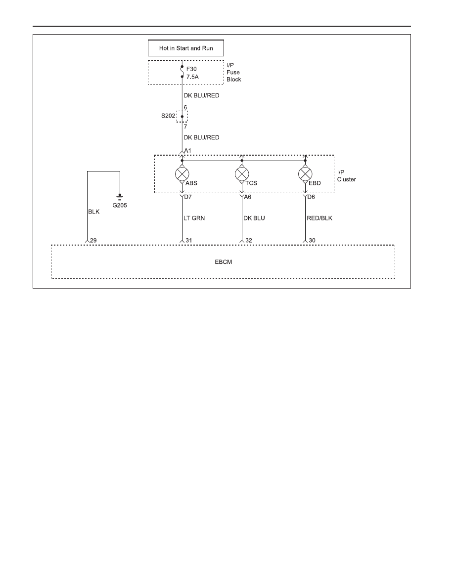
ELECTRONIC BRAKE-FORCE DISTRIBUTION SYSTEM (EBD)
INDICATOR LAMP INOPERATIVE
KAA4F120
Circuit Description
Battery voltage is supplied to the EBD warning lamp
with the ignition in ON or START. The warning lamp can
be activated only by the ABS control module internally
supplying ground to terminal 30.
Diagnosis
This procedure checks for a problem in the wiring, a
faulty ground, a voltage supply problem, a burned out
indicator lamp, or a contact problem in a connector.
Cause(s)
•
A fuse has blown.
•
The indicator lamp has burned out.
•
There is a corroded or broken connector terminal.
•
There is a faulty ground connection.
•
There is a broken wire in a wiring harness.
•
The EBCM is faulty.
Test Description
The number(s) below refer to step(s) on the diagnostic
table.
1. This test checks for any DTCs that may cause
the EBD indicator lamp to be inoperative.
2. This test verifies an inoperative lamp condition.
3. This test checks for voltage on the lamp circuit.
4. This begins a series of tests of the circuit from
the indicator lamp to the EBCM and ground.
19. This begins a series of tests of the voltage supply
circuits that power the indicator lamp.
Нет комментариевНе стесняйтесь поделиться с нами вашим ценным мнением.
Текст