SsangYong Korando II (1996-2006 year). Manual — part 212
SECTION 2D
REAR SUSPENSION
TABLE OF CONTENTS
Components Locator . . . . . . . . . . . 2D-2
Diagnostic Information and Procedures . . . ... 2D-3
Excessive Friction Check . . . . . . . . . . 2D-3
Repair Instructions . . . . . . . . . . . . 2D-4
On-Vehicle Service . . . . . . . . . . . . . 2D-4
Rear Stabilizer . . . . . . . . . . . . . . 2D-4
Rear Stabilizer Link . . . . . . . . . . . .. 2D-4
Rear Shock Absorber . . . . . . . . . . ... 2D-5
Lower Trailing Link . . . . . . . . . . . . 2D-5
Upper Trailing Link . . . . . . . . . . . . 2D-6
Rear Coil Spring . . . . . . . . . . . . ... 2D-6
Lateral Rod . . . . . . . . . . . . . . .. 2D-7
Specifications . . . . . . . . . . . . . ... 2D-8
Fastener Tightening Specifications . . . . . ... 2D-8
Special Tools and Equipment . . . . . . . ... 2D-9
Special Tools Table . . . . . . . . . . . ... 2D-9
SSANGYONG MY2002
2D-2 REAR SUSPENSION
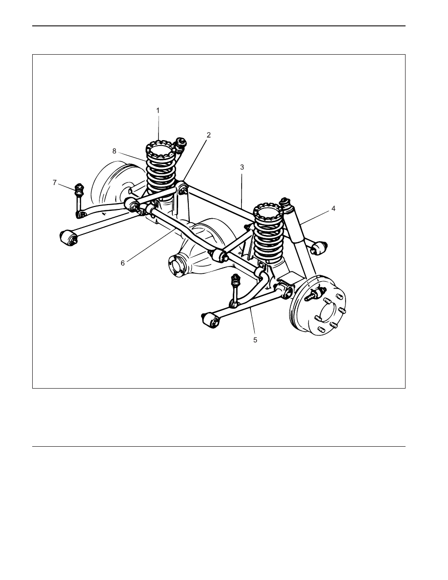
COMPONENT LOCATOR
1 Rear Coil Spring Seat
2 Upper Trailing Link
3 Lateral Rod
4 Rear Shock Absorber
5 Lower Trailing Link
6 Rear Stabilizer
7 Rear Stabilizer Link
8 Rear Coil Spring
KAA2D010
REAR SUSPENSION 2D-3
SSANGYONG MY2002
DIAGNOSTIC INFORMATION AND PROCEDURES
EXCESSIVE FRICTION CHECK
Ball Joint Inspection
Check excessive friction in the rear suspension as fol-
lows:
1. With the aid of a helper, lift up on the rear bumper
and raise the vehicle as high as possible. Slow
release the bumper and allow the car to assume
normal trim height.
2. Measure the distance from the floor to the center
of the bumper.
3. Push down on the bumper, release slowly, and
allow the car to assume normal trim height.
4. Measure the distance from the floor to the center
of the bumper.
The distance between the two measurements should
be less than 12.7 mm (0.50 inch). If the difference
exceeds this limit, inspect the control arms for damage
or wear.

SSANGYONG MY2002
2D-4 REAR SUSPENSION
ON-VEHICLE SERVICE
REAR STABILIZER
Removal and Installation Procedure
1. Raise and suitably support the vehicle.
2. Remove the rear stabilizer-to-rear stabilizer link nut.
Installation Notice
KAA2D020
KAA2D030
KAA2D040
3. Remove the rear stabilizer mounting bolts.
Installation Notice
4. Installation should follow the removal procedure in
the reverse order.
REPAIR INSTRUCTIONS
Tightening Torque
70 N•m (52 lb-ft)
Tightening Torque
38 N•m (28 lb-ft)
REAR STABILIZER LINK
Removal and Installation Procedure
1. Raise and suitably support the vehicle.
2. Remove the rear stabilizer link-to-body frame nut.
Installation Notice
•
The distance between the end of the nut and
the end of the rear stabilizer link should be 10 -
13 mm (0.39 - 0.51 inch) at the connection of
the rear stabilizer link and body.
Tightening Torque
38 N•m (28 lb-ft)
Нет комментариевНе стесняйтесь поделиться с нами вашим ценным мнением.
Текст