SsangYong Korando II (1996-2006 year). Manual — part 255

ABS AND TCS 4F-35
SSANGYONG MY2002
Check the EBCM connector.
Is it connected properly?
Connect the EBCM connector.
Is the repair complete?
1. Disconnect the EBCM connector.
2. Turn the ignition to ON.
3. Use an insulated tool to push the shorting bar in
the connector away from terminal 31.
Does the ABS indicator lamp go out?
Replace the ABS unit.
Is the repair complete?
Repair the short to ground in circuit Lg between I/P
cluster connector D7 and terminal 31 EBCM.
Is the repair complete?
Step
1
2
3
4
5
ABS INDICATOR LAMP ILLUMINATED CONTINUOUSLY, NO DTCS STORED
Action
Go to Step 3
System OK
Go to Step 4
System OK
System OK
Go to Step 2
-
Go to Step 5
-
-
-
-
-
-
-
Value(s)
Yes
No
SSANGYONG MY2002
4F-36 ABS AND TCS
SELF-DIAGNOSTICS
Important: The electronic brake control module (EBCM)
turns the valve relay off when a diagnostic trouble code
(DTC) is set. The scan tool will indicate that the valve
relay is off when it is used to monitor the data list. This
is normal and should not be considered a mal-function.
The EBCM performs system self-diagnostics and can
detect and often isolate system malfunctions. When it
detects a malfunction, the EBCM sets a DTC that repre
sents the malfunction, turns on the ABS and/or the
TCS indicators in most instances, and may disable the
ABS and/or the TCS functions, as necessary, for the
duration of the ignition cycle.
Once each ignition cycle, the EBCM performs an auto-
matic test when the vehicle reaches 2.75 km/h (1.7
mph). In the course of this test, the system cycles
each valve solenoid and the pump motor, along with
the necessary relays, to check component operation.
If the EBCM detects any malfunctions, it will set a
DTC as described above.
DISPLAYING DTCs
Tools Required
Scan Tool
DTCs can be read through the use of the scan tool.
CLEARING DTCs
Tools Required
Scan Tool
The diagnostic trouble codes (DTCs) in the electronic
brake control module (EBCM) memory are erased in
one of two ways:
•
Use the scan tool “Clear DTCs” selection.
•
After 249 DTC-free ignition cycles.
These two methods are detailed below. Be sure to verify
the proper system operation and, the absence of DTCs
when the clearing procedure is completed.
The EBCM will not permit DTC clearing until all DTCs
have been displayed. Also, DTCs cannot be cleared
by disconnecting the EBCM, disconnecting the battery
cables, or turning the ignition switch to LOCK.
Scan Tool Method
The scan tool can clear ABS/TCS system DTCs using
the mass storage cartridge.
1. Install the scan tool and the mass storage
cartridge.
2. Select “Fault Memory”.
3. Select “Clear Fault Memory”.
Clearing the fault memory cannot reset a valve relay
which was shut down when the fault was recognized.
Changes are possible only after the fault has been elimi-
nated and the next ignition cycle has begun.
Ignition Cycle Default
A DTC is erased from memory after 249 ignition cycles
without any reappearance of that malfunction.
INTERMITTENTS AND POOR
CONNECTIONS
As with most electronic systems, intermittent malfunc
tions may be difficult to diagnose accurately. The follow-
ing is a method to try to isolate an intermittent
malfunction, especially in wheel speed circuitry.
If an ABS malfunction occurs, the ABS indicator will
illuminate during the ignition cycle in which the
malfunction was detected. If it is an intermittent problem
which seems to have corrected itself (ABS indicator
OFF), a history DTC will be stored. Also stored will be
the history data of the DTC at the time the malfunction
occurred. Use the scan tool modular diagnostic system
to read ABS history data.
Most intermittents are caused by faulty electrical con
nections or wiring, although a sticking relay or solenoid
can occasionally be at fault.
ABS AND TCS 4F-37
SSANGYONG MY2002
BLANK
SSANGYONG MY2002
4F-38 ABS AND TCS
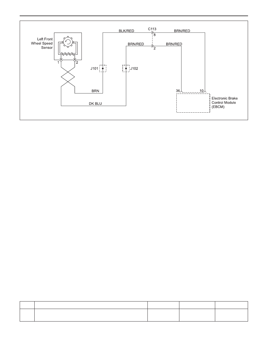
DIAGNOSTIC TROUBLE CODE (DTC) 03
LEFT FRONT WHEEL SPEED SENSOR FAULT
KAA4F140
Circuit Description
The toothed wheel generates a voltage pulse as it
moves past the sensor. Each tooth-gap-tooth series
on the wheel generates the pulses. The electronic brake
control module (EBCM) uses the frequency of these
pulses to determine the wheel speed. The voltage gen-
erated depends on the air gap between the sensor and
the toothed wheel, and on the wheel speed.
Diagnosis
This procedure checks for a malfunctioning wheel speed
sensor, a short to ground or to voltage in the wiring, or
a contact problem in a connector.
Cause(s)
•
The wheel speed sensor is defective.
•
There is a problem in the wiring.
•
There is a problem with a connector.
Fail Action
ABS action is disabled, and the ABS warning lamp is
ON.
Test Description
The number(s) below refer to step(s) on the diagnostic
table.
1. This step begins an examination for a defective
wheel speed sensor.
6. This step tests the wiring for a short to voltage.
8. This step tests the wiring for a short to ground.
10. This step tests for an open or a high resistance in
the wiring.
Diagnostic Aids
Be sure that the speed sensor wiring is properly routed
and retained. This will help to prevent false signals due
to the pickup of electrical noise.
It is very important to perform a thorough inspection of
the wiring and the connectors. Failure to inspect the
wiring and the connectors carefully and completely may
result in misdiagnosis, causing part replacement with
the reappearance of the malfunction.
Use the scan tool to monitor wheel speeds during a
road test. Watch the wheel speeds being displayed on
the scan tool to see if any of the readings are unusual,
such as one sensor varying in speed from the other
three, a signal going intermittently high or low, etc. If
this does not identify the intermittent, wet the speed
sensor harness on the underside of the vehicle and
perform a road test, monitoring wheel speeds with the
scan tool.
Step
1
DTC 03 - Left Front Wheel Speed Sensor Fault
Action
Yes
Go to Step 3
No
Go to Step 2
Value(s)
-
Examine the wheel speed sensor.
Are there any signs of physical damage?
Нет комментариевНе стесняйтесь поделиться с нами вашим ценным мнением.
Текст