SsangYong Korando II (1996-2006 year). Manual — part 164
OM600 ENGINE MECHANICAL 1B3 -- 105
DAEWOO MY_2000
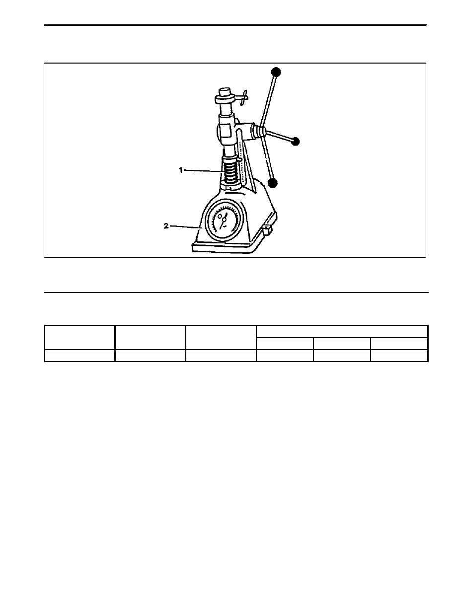
VALVE SPRINGS CHECK
Preceding Work : Removal of valve spring
1 Valve Spring
2 Spring Scale
Service Data
Outer diameter
Wire diameter
Free length
At preloaded
Outer diameter
Wire diameter
Free length
Length
Tension (new)
Limit
33.1 mm
4.20 mm
50.0 mm
27 mm
680 -- 740 N
612 N
1B3 -- 106 OM600 ENGINE MECHANICAL
DAEWOO MY_2000
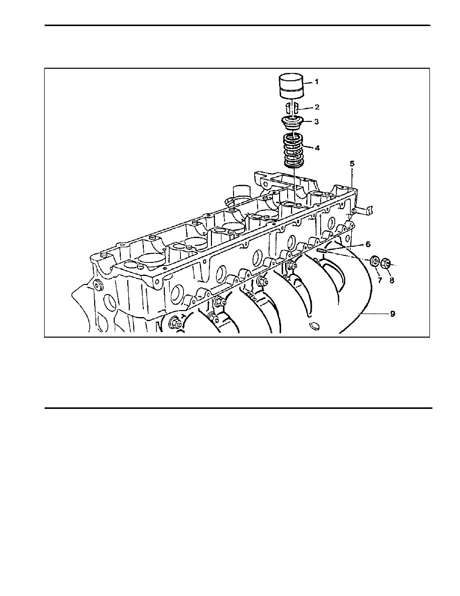
VALVE SPRINGS (CYLINDER HEAD REMOVED)
Cylinder Head Removed
1 Valve Tappet
2 Valve Cotters
3 Spring Retainer
4 Valve Spring
Check, replace if necessary
. . . .
5 Cylinder Head
6 Stud Bolt
12N∙m (106 lb-in)
. . . . . . . . . . . . . . . .
7 Washer
8 Nut
Replace, 25N∙m (18 lb-ft)
. . . . . . . . . . . . . .
9 Exhaust Manifold
OM600 ENGINE MECHANICAL 1B3 -- 107
DAEWOO MY_2000
Tools Required
102 589 03 40 00 Magnetic Bar
116 589 06 63 00 Magnetic Finger
601 589 01 59 00 Assembling Board
601 589 02 59 00 Supporting Bridge
667 589 00 31 00 Press Lever
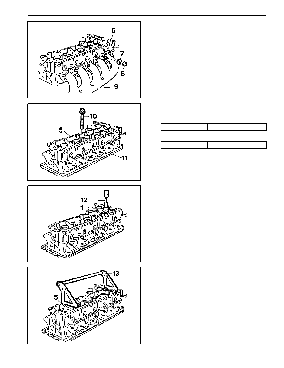
Removal & Installation Procedure
1. Remove the nuts (8) uniformly and then remove the
washer (7), exhaust manifold (9) and gasket.
Installation Notice
Check the stud bolt (6) for damage and replace if
necessary.
Tightening Torque
12 N∙m (106 lb-in)
Replace the gasket and tighten the nuts (8).
Tightening Torque
25 N∙m (18 lb-ft)
2. Install the assembling board (11) to the cylinder
head with 4 cylinder head blots (10).
Assembling Board 601 589 01 59 00
3. Pull out the valve tappet (1) with magnetic bar (12).
Notice
Place the valve tappets upside down (open end up-
ward).
Magnetic Bar 102 589 03 40 00
4. Install the supporting bridge (13) on the cylinder
head (5).
Supporting Bridge 601 589 02 59 00
1B3 -- 108 OM600 ENGINE MECHANICAL
DAEWOO MY_2000
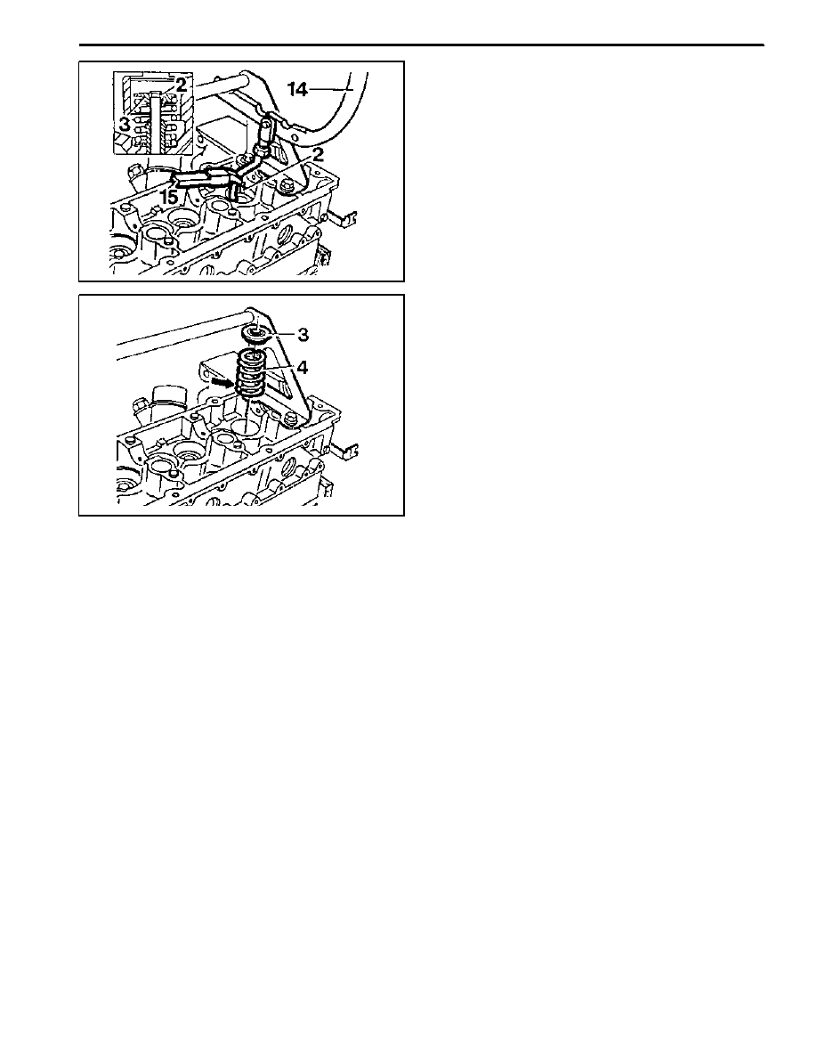
5. Using the press lever (14), press the spring retainer
downward and remove the valve cotters (2) with
magnetic finger (15).
Notice
Be careful not to damage guide bore of the valve
tappet.
Press Lever 667 589 00 31 00
Magnetic Finger 116 589 06 63 00
6. Remove the spring retainer (3) and spring (4).
Installation Notice
Install the valve spring with the color coding (arrow)
facing down.
7. Check the valve spring and replace if necessary.
8. Installation should follow the removal procedure in
the reverse order.
Нет комментариевНе стесняйтесь поделиться с нами вашим ценным мнением.
Текст