SsangYong Korando II (1996-2006 year). Manual — part 66
M162 ENGINE CONTROLS 1F1 -- 99
DAEWOO MY_2000
KAA1F440
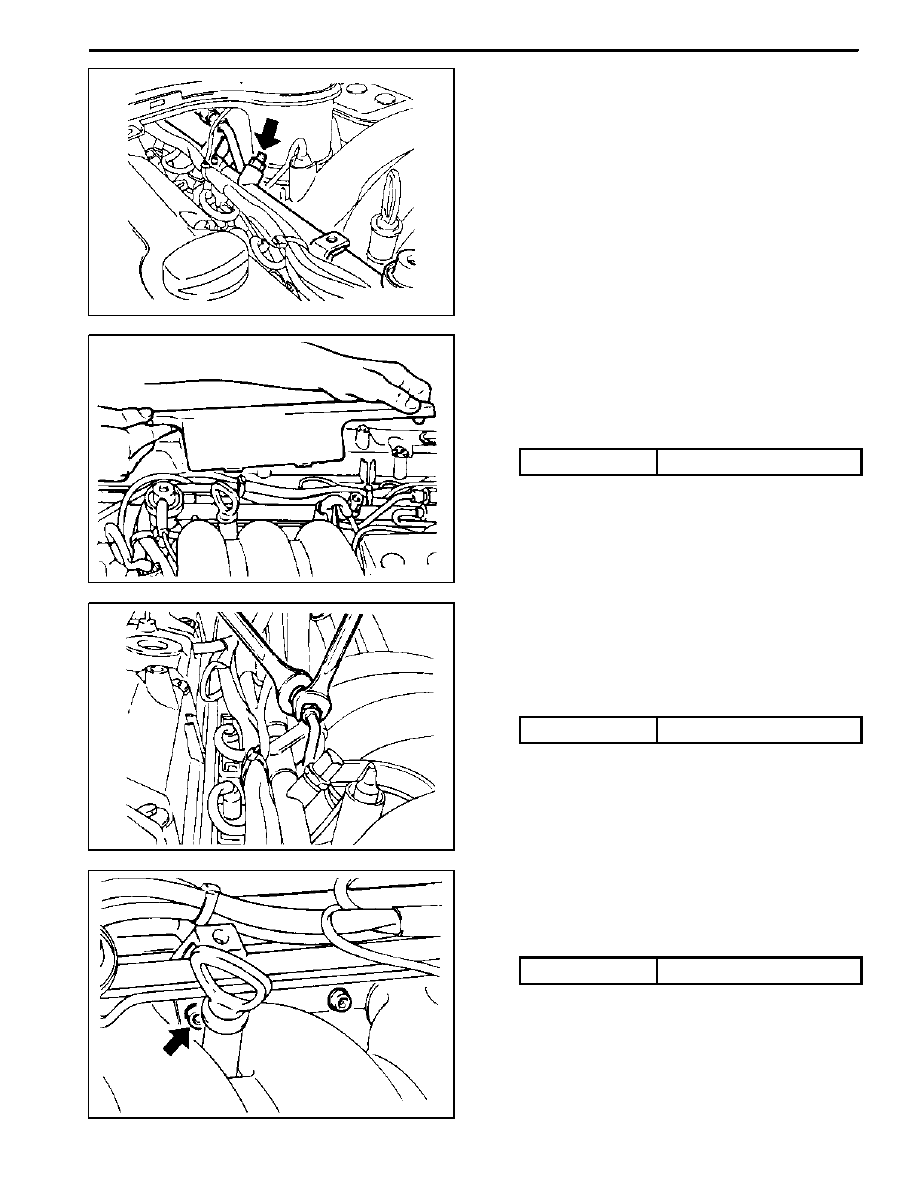
FUEL RAIL AND INJECTORS
Removal and Installation Procedure
Caution: The fuel system is under pressure. To
avoid fuel spillage and the risk of personal injury or
fire, it is necessary to relieve the fuel system pres-
sure before disconnecting the fuel lines.
1. Discharge the fuel pressure from the fuel pressure
test connector.
2. Disconnect the negative battery cable.
3. Disconnect the vacuum hose from the fuel pressure
regulator.
KAA1F060
4. Remove the cable guide.
5. Disconnect the Hot Film Air Mass (HFM) sensor
connector.
6. Remove the intake air duct mounting bolts.
Installation Notice
Tightening Torque
9 NSm (80 Ib-in)
7. Remove the intake air duct clamps.
8. Remove the intake air duct.
KAA1F070
9. Remove the fuel return and supply line.
Notice: For removal, cover around parts with cloths not
to be stained by fuel. In case of checking the injector
only, do not remove the fuel return and supply line.
Installation Notice
Tightening Torque
23 NSm (17 Ib-ft)
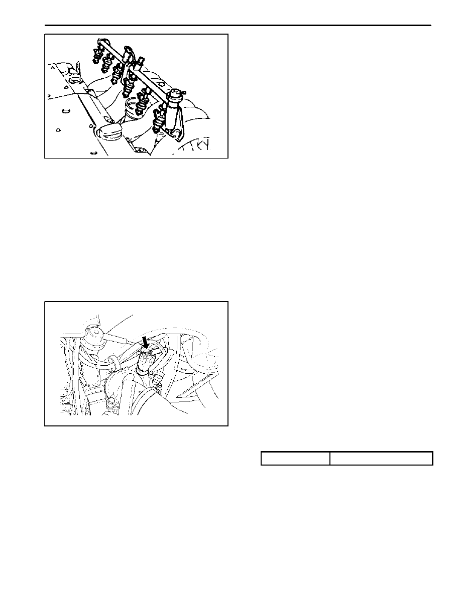
10. Remove the six injector connectors.
KAA1F080
11. Remove the two left and two right bolts and one cen-
ter bolt of the fuel rail assembly from the intake man-
ifold.
Installation Notice
Tightening Torque
25 NSm (18 Ib-ft)
1F1 -- 100 M162 ENGINE CONTROLS
DAEWOO MY_2000
KAA1F090
Notice: Before removal, the fuel rail assembly may be
cleaned with a spray-type cleaner, following package in-
structions. Do not immerse the fuel rails in liquid clean-
ing solvent. Use care in removing the fuel rail assembly
to prevent damage to the electrical connectors and in-
jector spray tips. Prevent dirt and other contaminants
from entering open lines and passages. Fittings should
be capped and holes plugged during service.
Important: If an injector becomes separated from the
rail and remains in the cylinder head, replace the injector
O-ring seals and the retaining clip.
12. Remove the injectors and the fuel rail carefully.
13. Remove the fuel injector retainer clips.
14. Remove the fuel injectors by pulling them down and
out.
15. Discard the fuel injector O-rings.
16. Lubricate the new fuel injector O-rings with engine
oil. Install the new O-rings on the fuel injectors.
17. Perform a leak check of the fuel rail and fuel injec-
tors.
18. Installation should follow the removal procedure in
the reverse order.
YAA1F150
ENGINE COOLANT TEMPERATURE
SENSOR
Removal and Installation Procedure
1. Relieve the coolant system pressure.
2. Disconnect the negative battery cable.
3. Disconnect the engine coolant temperature sensor
connector.
Notice: Take care when handling the engine coolant
temperature sensor. Damage to the sensor will affect
the proper operation of the fuel injection system.
4. Remove the engine coolant temperature sensor
from the pump hosing.
Installation Notice
Tightening Torque
30 NSm (22 Ib-ft)
5. Installation should follow the removal procedure in
the reverse order.
M162 ENGINE CONTROLS 1F1 -- 101
DAEWOO MY_2000
KAA1C010
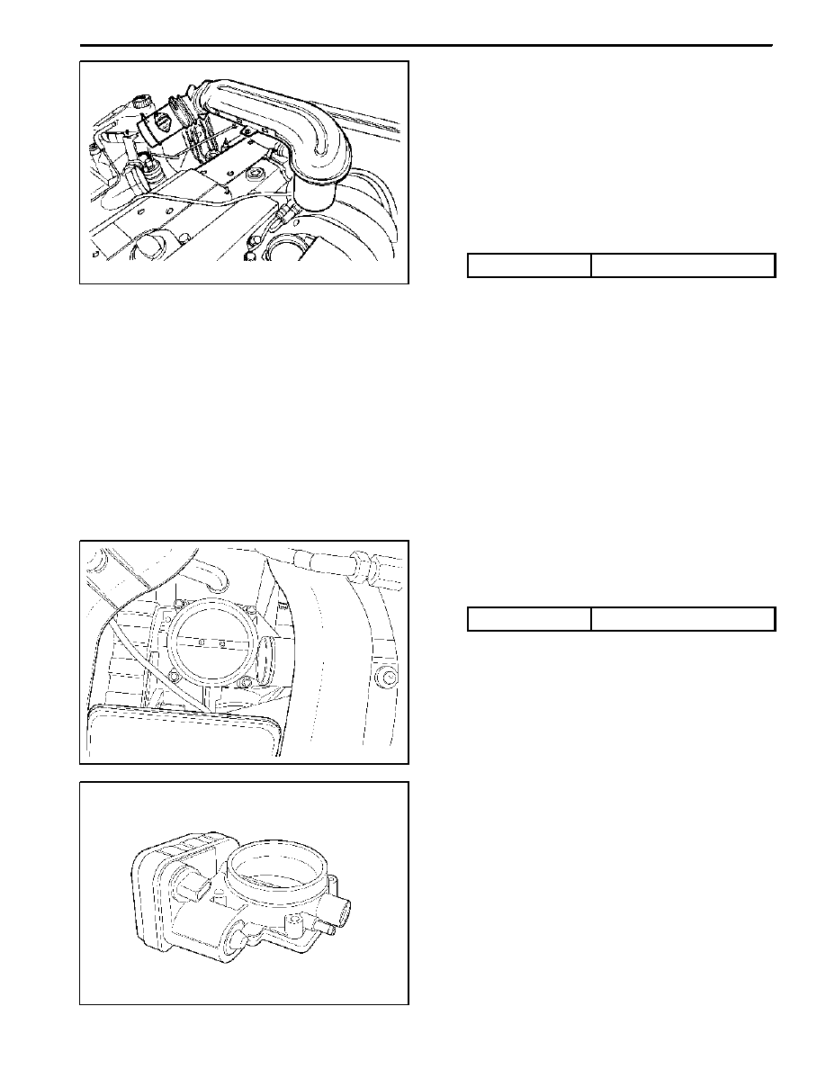
THROTTLE BODY (INTEGRATED
WITH THE ACTUATOR)
Removal and Installation Procedure
1. Disconnect the negative battery cable.
2. Disconnect the mass air flow sensor connector.
3. Disconnect the mass air flow sensor from the air fil-
ter housing.
4. Remove the intake air duct mounting bolts.
Installation Notice
Tightening Torque
9 NSm (80 lb-in)
5. Remove the air inlet housing clamps.
6. Remove the inlet air housing.
KAA1D230
7. Disconnect the throttle body electrical connector.
8. Remove the throttle body bolts.
Installation Notice
Tightening Torque
12 NSm (106 lb-in)
9. Remove the vacuum hose.
KAA1D240
10. Remove the throttle body and discard the gasket.
Important: Use care in cleaning old gasket material.
Sharp tools may damage sealing surfaces.
11. Installation should follow the removal procedure in
the reverse order.
1F1 -- 102 M162 ENGINE CONTROLS
DAEWOO MY_2000
KAA1F190
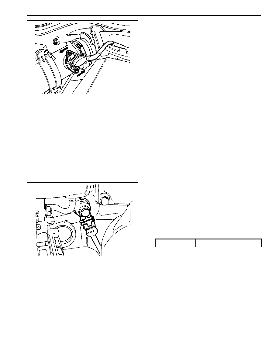
HOT FILM AIR MASS (HFM) SENSOR
Removal and Installation Procedure
1. Disconnect the negative battery cable.
2. Disconnect the Hot Film Air Mass (HFM) sensor
electrical connector.
3. Remove the HFM sensor retaining screws.
4. Turn the HFM sensor coupling in the direction
shown in the figure in the left so that it gets sepa-
rated from the contact surface.
Notice: Make sure the HFM sensor coupling connects
completely with the contact surface installation.
5. Remove the HFM sensor.
6. Installation should follow the removal procedure in
the reverse order.
KAA1F180
KNOCK SENSOR
Removal and installation Procedure
1. Disconnect the negative battery cable.
2. Disconnect the knock sensor electrical connector
from the intake manifold bracket.
3. Remove the knock sensor mounting bolt from the
knock sensor installed on the cylinder block.
Installation Notice
Tightening Torque
25 NSm (18 Ib-ft)
4. Remove the knock sensor.
5. Installation should follow the removal procedure in
the reverse order.
Нет комментариевНе стесняйтесь поделиться с нами вашим ценным мнением.
Текст