SsangYong Korando II (1996-2006 year). Manual — part 67
M162 ENGINE CONTROLS 1F1 -- 103
DAEWOO MY_2000
KAA1F410
PEDAL POSITION SENSOR
Removal and installation Procedure
1. Disconnect the negative battery cable.
2. Disconnect the pedal position sensor connector.
3. Unscrew the bolts and nut.
Installation Notice
Tightening Torque
6 NSm (53 lb-in)
4. Remove the pedal and sensor assembly.
5. Installation should follow the removal procedure in
the reverse order.
YAA1F220
OXYGEN SENSOR
Removal and Installation Procedure
1. Disconnect the negative battery cable.
Notice: The oxygen sensor uses a permanently at-
tached pigtail and connector. This pigtail should not be
removed from the oxygen sensor. Damage or removal
of the pigtail or the connector could affect proper opera-
tion of the oxygen sensor. Do not drop the oxygen sen-
sor.
2. Disconnect the electrical connector.
3. Carefully remove the oxygen sensor from the exhaust
pipe.
Installation Notice
Tightening Torque
55 NSm (41 Ib-ft)
Important: A special anti-seize compound is used on
the oxygen sensor threads. This compound consists of
a liquid graphite and glass beads. The graphite will burn
away, but the glass beads will remain, making the sen-
sor easier to remove. New or serviced sensors will al-
ready have the compound applied to the threads. If a
sensor is removed from any engine and is to be rein-
stalled, the threads must have an anti-seize compound
applied before reinstallation.
4. Coat the threads of the oxygen sensor with an anti-
seize compound, if needed.
5. Installation should follow the removal procedure in
the reverse order.

1F1 -- 104 M162 ENGINE CONTROLS
DAEWOO MY_2000
KAB1F380
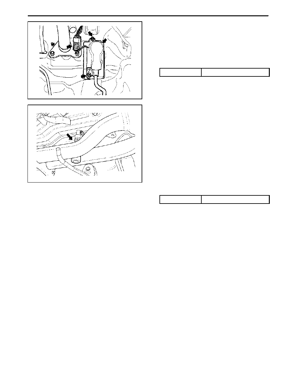
PURGE CONTROL VALVE
Removal and Installation Procedure
1. Disconnect the negative battery cable.
2. Disconnect the purge control valve connector.
3. Disconnect the throttle body-to-purge control valve
hose from the purge control valve.
4. Disconnect the canister-to-purge control valve hose
from the purge control valve.
5. Remove the purge control valve.
6. Installation should follow the removal procedure in
the reverse order.
KAB1F390
CANISTER
Removal and Installation Procedure
Caution: Canister and vacuum hoses contain fuel
vapors. Do not smoke in the area or permit an open
flame.
1. Disconnect the fuel tank-to-canister hose form the
canister.
2. Disconnect the canister-to-purge control valve hose
form the canister.
KAB1F380
3. Remove the canister mounting bolts.
Installation Notice
Tightening Torque
6 NSm (53 lb-in)
4. Remove the canister.
5. Installation should follow the removal procedure in
the reverse order.
KAA1C170
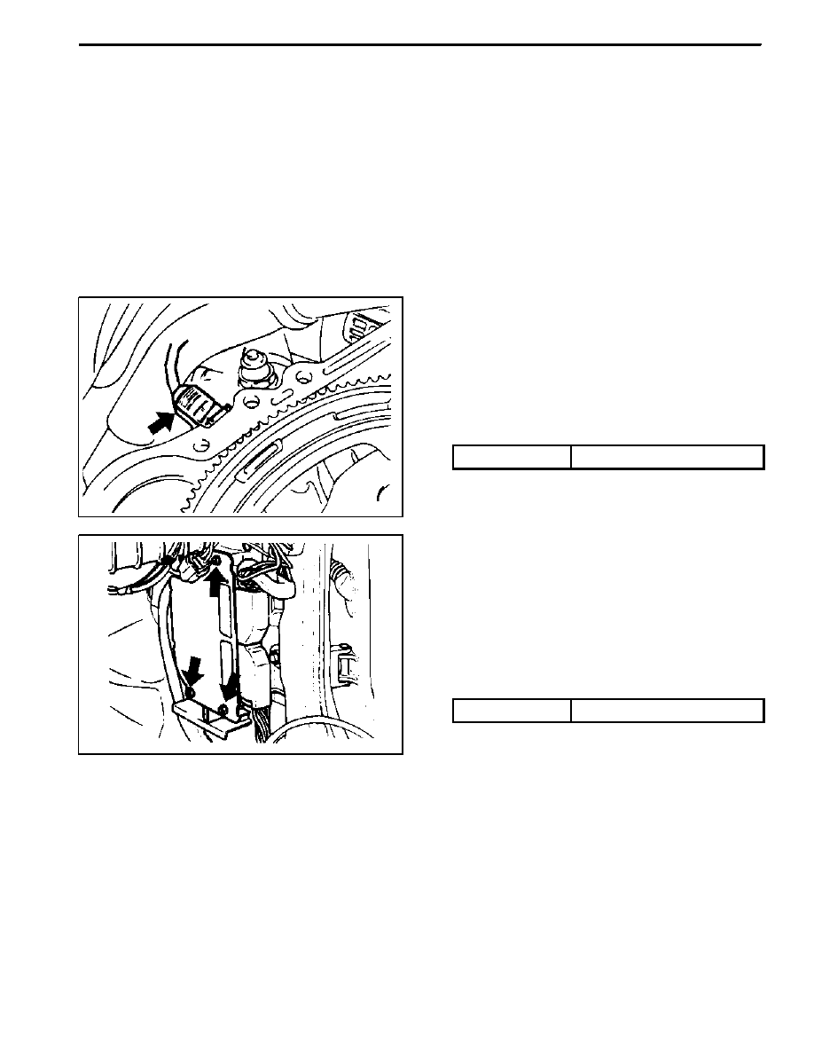
CAMSHAFT POSITION SENSOR
Removal and Installation Procedure
1. Disconnect the negative battery cable.
2. Disconnect the electrical connector from the cam-
shaft position sensor.
3.Remove the camshaft position sensor retaining bolt.
Installation Notice
Tightening Torque
10 NSm (89 Ib-in)
M162 ENGINE CONTROLS 1F1 -- 105
DAEWOO MY_2000
4. Check the O-ring for damage and replace it if neces-
sary.
5. Installation should follow the removal procedure in
the reverse order.
KAA1F160
CRANKSHAFT POSITION SENSOR
Removal and installation Procedure
1. Disconnect the negative battery cable.
2. Disconnect the electrical connector at the crankshaft
position sensor.
3. Remove the crankshaft position sensor retaining bolt.
Installation Notice
Tightening Torque
10 NSm (89 lb-in)
4. Installation should follow the removal procedure in
the reverse order.
KAA1F200
ENGINE CONTROL MODULE
Removal and installation Procedure
1. Disconnect the negative battery cable.
2. Remove the cowl side trim form passenger side. Re-
fer to Section 9G, Interior trim.
3. Remove the four securing nuts for the Engine Control
Module (ECM) from the mounting bracket.
Installation Notice
Tightening Torque
10 NSm (89 lb-in)
4. Pull out the ECM from the bracket.
5. Disconnect the vehicle side coupling.
6. Installation should follow the removal procedure in
the reverse order.
DAEWOO MY_2000
SECTION 1G1
M162 ENGINE INTAKE & EXHAUST
CAUTION: Disconnect the negative battery cable before removing or installing any electrical unit or when a
tool or equipment could easily come in contact with exposed electrical terminals. Disconnecting this cable
will help prevent personal injury and damage to the vehicle. The ignition must also be in LOCK unless other-
wise noted.
TABLE OF CONTENTS
Specifications
1G1--2
. . . . . . . . . . . . . . . . . . . . . . . . . . .
Fastener Tightening Specifications
1G1--2
. . . . . . . . .
Maintenance and Repair
1G1--3
. . . . . . . . . . . . . . . . . .
On--Vehicle Service
1G1--3
. . . . . . . . . . . . . . . . . . . . . . . .
Air Cleaner
1G1--3
. . . . . . . . . . . . . . . . . . . . . . . . . . . . .
Intake Air Duct
1G1--5
. . . . . . . . . . . . . . . . . . . . . . . . . .
Intake Manifold
1G1--7
. . . . . . . . . . . . . . . . . . . . . . . . .
Resonance Flap
1G1--9
. . . . . . . . . . . . . . . . . . . . . . . . .
Exhaust Manifold
1G1--11
. . . . . . . . . . . . . . . . . . . . . . .
Нет комментариевНе стесняйтесь поделиться с нами вашим ценным мнением.
Текст