SsangYong Korando II (1996-2006 year). Manual — part 223

PROPELLER SHAFT 3C-3
SSANGYONG MY2002
PROPELLER SHAFT
Inspection Procedure
1. Visually check the propeller shaft.
2. Using a dial indicator, measure propeller shaft
runout by turning the shaft. If runout exceeds limit,
replace the propeller shaft or correct it.
Adjustment Notice
DIAGNOSTIC INFORMATION AND PROCEDURES
KAA3C020
Specification
0.4 mm (0.016 inch)
3. Measure the universal joint starting torque.
Adjustment Notice
Specification
0.54 N•m (4.78 lb-in)
KAA3C030
4. Measure the spider outer diameter.
Adjustment Notice
Specification
16.668 mm (0.656 inch)
KAA3C040
4. Measure the spider outer diameter.
Adjustment Notice
Specification
0.064 mm (0.0025 inch)
KAA3C050
SSANGYONG MY2002
3C-4 PROPELLER SHAFT
KAA3C070
KAA3C080
KAA3C060
ON-VEHICLE SERVICE
FRONT PROPELLER SHAFT
Removal and Installation Procedure
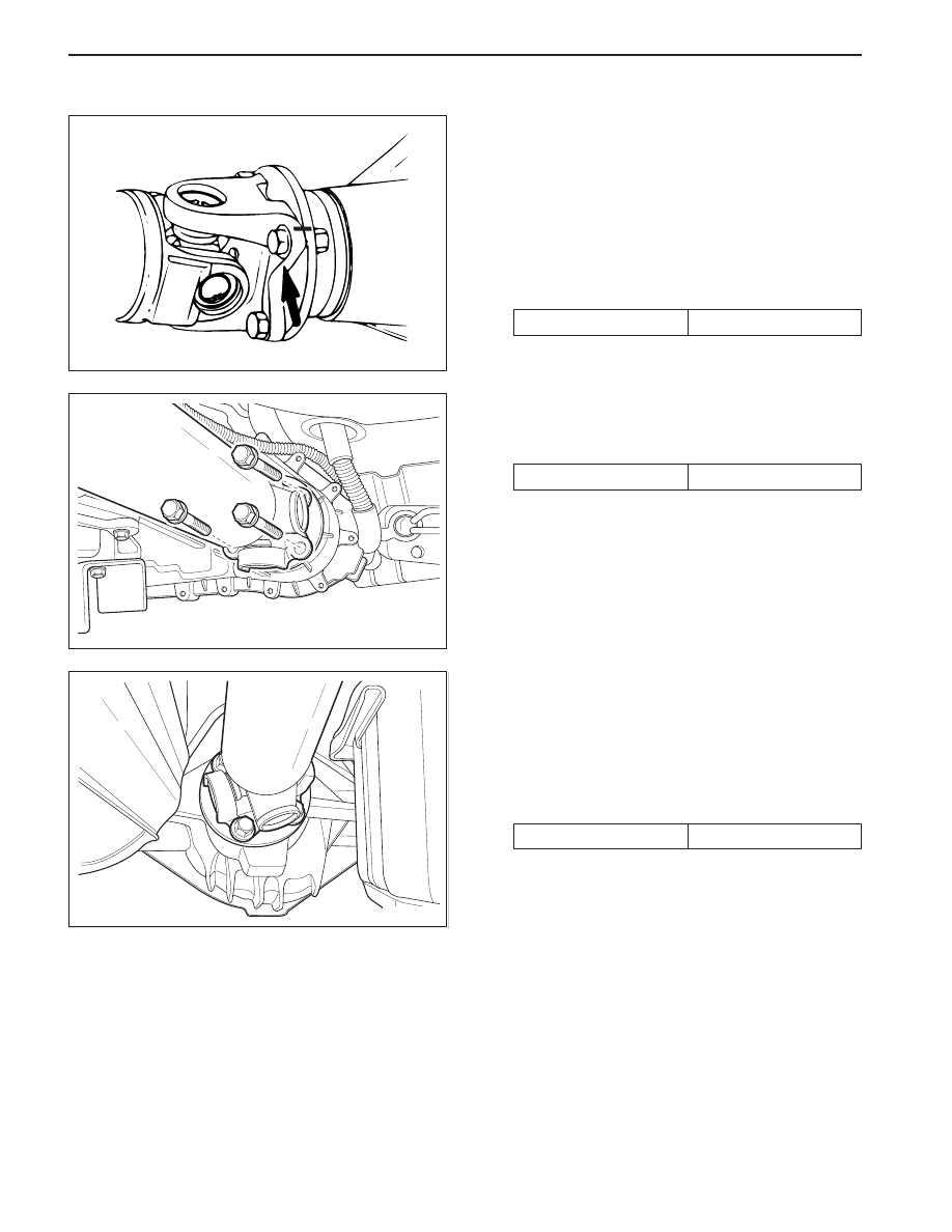
1. Raise and suitably support the vehicle.
2. Remove the front propeller shaft-to-front axle
assembly bolts.
Installation Notice
REPAIR INSTRUCTIONS
Tightening Torque
7.0 - 8.5 kg•m
•
Make alignment marks on the front propeller
shaft and front axle housing.
3. Remove the front propeller shaft-to-transfer case
bolts.
Installation Notice
Tightening Torque
8.1 - 8.9 kg•m
4. Remove the front propeller shaft.
5. Installation should follow the removal procedure in
the reverse order.
REAR PROPELLER SHAFT
Removal and Installation Procedure
1. Raise and suitably support the vehicle.
2. Remove the rear propeller shaft-to-rear axle assem-
bly bolts.
Installation Notice
Tightening Torque
7.0 - 8.5 kg•m
•
Make alignment marks on the rear propeller
shaft and rear axle housing.
PROPELLER SHAFT 3C-5
SSANGYONG MY2002
KAA3C090
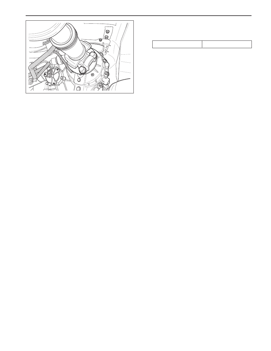
3. Remove the rear propeller shaft-to-transfer case
bolts.
Installation Notice
Tightening Torque
8.1 - 8.9 kg•m
4. Remove the rear propeller shaft.
5. Installation should follow the removal procedure in
the reverse order.

SSANGYONG MY2002
3C-6 PROPELLER SHAFT
UNIT REPAIR
PROPELLER SHAFT
Removal and Installation Procedure
1. Remove the front propeller shaft. Refer to “Front
Propeller Shaft” in this section.
2. Place alignment marks before removing the spider.
KAA3C100
KAA3C120
KAA3C110
KAA3C130
3. Using a snap ring pliers, remove the snap ring.
4. Slightly tapping the yoke shoulder using a brass
hammer, remove the bearing. Remove the
remaining bearings in the same way.
5. Disassemble the universal joint parts.
Installation Notice:
•
Clean the disassembled parts and replace them
if damaged.
•
Apply grease to the inner of the bearing cap of
the needle roller bearing and assemble the needle
roller.
Grease
EP#2
Нет комментариевНе стесняйтесь поделиться с нами вашим ценным мнением.
Текст