SsangYong Musso. Manual — part 514

TRANSFER CASE (TOD) 5D2-3
T
.C.C.U
5D2-4 TRANSFER CASE (TOD)
FUNCTION DESCRIPTION
!
!
!
!
!
TOD System Select Mode (4H and 4L)
4H is the mode when drive normally of which gear ratio is 1:1 and 4L mode distributes power to front and rear
wheels 50:50 of which gear ratio is 2.48:1.
!
!
!
!
!
TOD System Function (select 4H mode)
TOD system controls clutch mechanism to comply with rotation in front and rear propeller shaft and if its difference
exceeds the permissible range, corresponding power is distributed into front wheel through EMC (Electro-Magnetic
Clutch).
Hall effect sensor signals speed on front and rear propeller shafts going through with TOD control unit.
Transfercase clutch coil is activated by variable current on exceeding difference of speed in front and rear propeller
shafts.
!
!
!
!
!
Function of 4L Mode
When select 4L mode, EMC is locked to apply maximum torque into front and rear propeller shafts. Shift motor
rotates also 4L position by rotation of cam thus propeller shaft torque changes from 1:1 to 2.48:1 by planetary
gear set.
!
!
!
!
!
Shift Motor
It locates backside transfer case, which drives rotary helical cam.
When mode select switch changes to 4L, shift fork is on position for 2.48:1 by rotation of helical cam.
!
!
!
!
!
Transfer Case
TOD transfer case distributes power into front and rear axle by operation of 4H/4L switch and shift motor.
Shifting 4H to 4L, is performed towards reducing HI-LO collar by means for connection HI-LO shift fork with
output shaft in order to join with planetary gear. Torque transmits input shaft then sun gear rotating front planetary
gear. Front planetary gear join with output shaft and drives LO position.
TRANSFER CASE (TOD) 5D2-5
Definitions
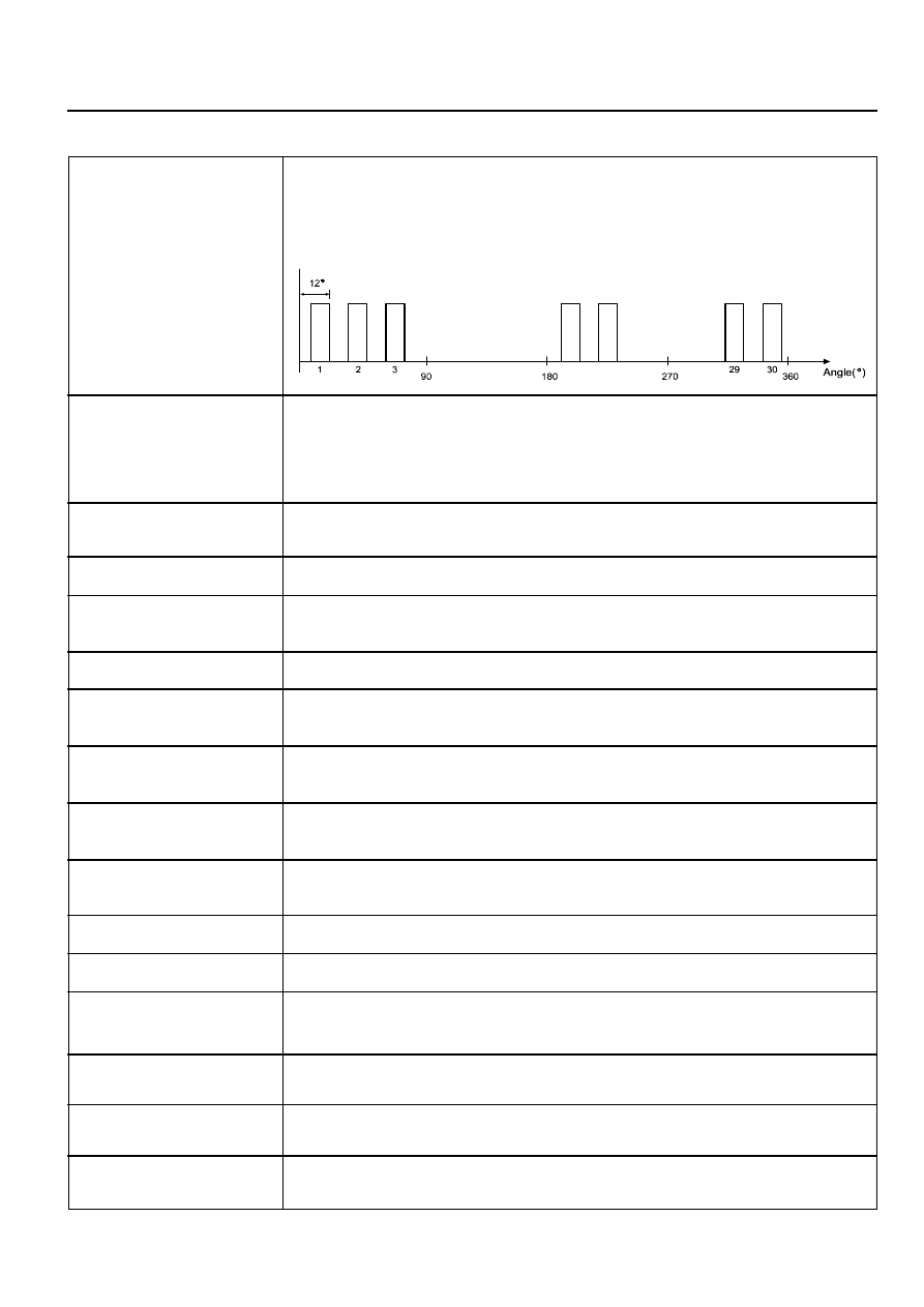
Rear Speed Sensor
A Hall Effect speed sensor which produces a square wave. 0-5Vdc signal in
response to a rotating 30 tooth wheel coupled to the rear propshaft inside the
Transfer Case. Each rotation of the rear propshaft will result in 30 speed sensor
pulse.
Front Speed Sensor
A Hall Effect speed sensor which produces a square wave. 0-5Vdc signal in
response to a rotating 30 tooth wheel coupled to the front propshaft inside the
Transfer Case. Each rotation of the front propshaft will result in 30 speed sensor
pulse.
EMC
An Electromagnetic clutch used to control the amount of torque applied to the
front propshaft.
TOD
TM
Torque on Demand
TM
.
Duty Cycle
Duty Cycle is the time the EMC is on divided by the period in which it is being
modulated.
Touch-off
A minimum amount of duty cycle applied to the EMC.
Front Overrun
A condition where the front propshaft is turning at a rate which is faster than the
rear propshaft.
Rear Overrun
A condition where the rear propshaft is turning at a rate which is faster than the
front propshaft.
High Range
The highest (numerically lowest = 1 :1) gear ratio between the input and outputs
of the Transfer Case.
Low Range
The lowest (numerically highest = 2.48:1) gear ratio between the input and outputs
of the Transfer Case.
4H/4L Switch
A switch which selects the desired gear ratio.
Shift Motor
Electric motor which changes the Transfer Case range.
Position Encoder
A set of 4 Gray code switches which provide feedback to the TCCU indicating the
position of the Shift Motor.
Clutch Interlock Switch
A switch on vehicles equipped with a manual transmission which indicates that
the clutch pedal is depressed.
Neutral Safety Switch
A switch on vehicles equipped with an automatic transmission which indicates
that the transmission is in neutral.
Shift Inhibit Speed
The vehicle speed above which Transfer Case shifts are disallowed. Vehicle speed
is indicated by propshaft speed measurement.
5D2-6 TRANSFER CASE (TOD)
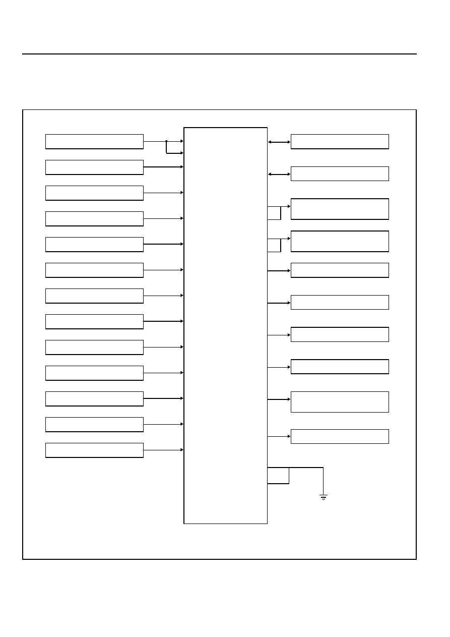
Input/Output diagram
TOD control unit and main wiring harness is linked by 30 pin
connector. Each pin joins with switche and actuator whose
details refer to the below diagram.
Battery Power
Ignition ON/OFF
Position Encoder 1
Position Encoder 2
Position Encoder 3
Position Encoder 4
4H / 4L Switch Signal
A/T “N” Position Signal
Speed / TPS Supply
Front Speed Sensor Input
Rear Speed Sensor Input
ABS Operation Signal
Brake Switch Signal
4
5
27
10
28
30
9
24
16
11
29
25
26
19
CAN H
CAN L
Shift Motor output port
(LO-HI)
Shift Motor output port
(HI-LO)
EMC
'4L' Indicator
Position Return
'4WD CHECK' IND
TPS/speed Sensor Ground
(Speed / TPS Return)
2
1
3
21
6
7
13
15
14
K-Line
20
22
23
17
18
Нет комментариевНе стесняйтесь поделиться с нами вашим ценным мнением.
Текст