SsangYong Musso. Manual — part 512
5D1-32 TRANSFER CASE (PART TIME 4408)
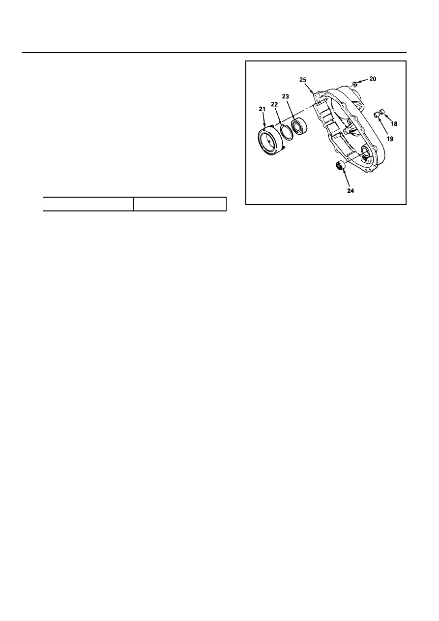
Cover
1. Position the cover to be the open end up on the work table.
2. Position the end of needle bearing to be identification mark
up and press into the cover until upper end of bearing is
40.47 - 40.97mm below cover face that contacts with transfer
case.
3. Press the ball bearing into the cover and install the snap
ring .
4. Install remaining parts as follows.
!
Install the 4 O-rings on the stud bolts of the clutch coil
assembly.
!
Install the clutch coil assembly inside the cover and
tighten 3 nuts.
18
Oil Seal
19
Bushing
20
Nut
21
Clutch Coil Assembly
22
Snap Ring
23
Ball Bearing
24
Needle Bearing
25
Cover
Tightening Torque
8 - 11 Nm
!
Install the bearing and motor bearing into the cover.
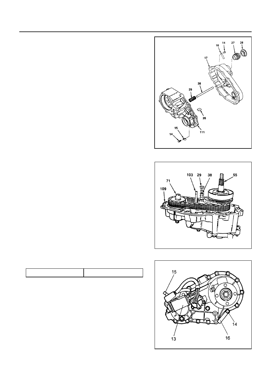
TRANSFER CASE (PART TIME 4408) 5D1-33
4. Install the cover onto the transfer case as follows :
!
Align the cover bores with transfer case pins.
!
Align the cover bearings with output shafts.
!
Align the cover blind hole with rail shaft and make sure
that return spring is not cocked.
29
Return Spring
38
Rail Shaft
55
Output Shaft
71
Front Output Shaft
103
Shift Shaft
109
Dowel Pin
Cover Assembly
14
Bolt
15
Wiring Clip
16
Identification Tag
17
Cover Assembly
26
Magnet
27
Speed Gear
28
Oil Seal
29
Return Spring
38
Rail Shaft
111
Case
1. Install the return spring over rail shaft in the transfer case.
2. Insert the magnet into the transfer case slot.
3. Apply 1.6mm bead of Loctite RTV 598 to the transfer case
mounting surface.
Notice
For installation of cover, align the transfer case with cover
not to use excessive force.
13
Motor Assembly
14
Bolt
15
Wiring Clip
16
Identification Tag
5. Tighten 9 bolts positioning identification tag and wiring clip.
6. Install the speed gear over output shaft spline in the cover
assembly.
7. Press the new oil seal into the cover assembly.
Tightening Torque
28 - 48 Nm
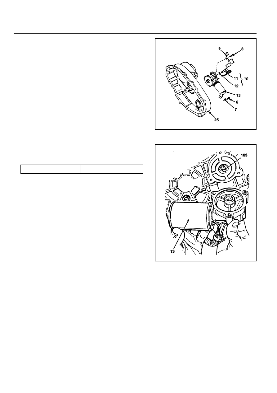
5D1-34 TRANSFER CASE (PART TIME 4408)
External Electric Shift
1. Align the motor with shift shaft and position the motor
assembly onto the cover.
2. Install the motor to the shift shaft and contact cover androtate
the motor clockwise direction to check correctengagement.
6
Bolt
7
Washer
8
Bolt
9
Sensor and Harness Bracket
10
Sensor Assembly
14
Speed Sensor
12
O-ring
13
Motor Assembly
25
Cover
13
Motor Assembly
103
Shift Shaft
3. Insert the 0-ring on the speed sensor speed sensor
assembly to the cover.
4. Install the bracket to the motor assembly and tighten 3bolts.
Tightening Torque
8 -11 Nm

TRANSFER CASE (PART TIME 4408) 5D1-35
Companion Flange
1. Install the 2 plugs to the cover.
2. Install the companion flange, oil seal and washer.
3. Holding the companion flange, tighten the nut.
1
Nut
2
Washer
3
Oil Seal
4
Companion Flange
5
Plug
25
Cover
Notice
Apply Loctite 262 to nut before installation.
Tightening Torque
346 - 380 Nm
Нет комментариевНе стесняйтесь поделиться с нами вашим ценным мнением.
Текст