SsangYong Musso. Manual — part 286

M161 ENGINE MECHANICAL 1B2-71
Adjustment Procedure
1. Position the NO.1 cylinder to ATDC 20° .
2. Remove the chain tensioner.
3. Remove the exhaust camshaft sprocket.
4. Adjust the timing position with inserting the insert pin
(f6.5mm, 111 589 03 15 00) into the NO.1 and NO.4
camshaft bearing cap hole and flange hole while rotating
the camshaft by using wrench (104 589 01 01 00).
5. Install the chain to the intake camshaft sprocket.
6. Install the chain to the exhaust camshaft sprocket and
tighten the bolt.
Installation Notice
Tightening Torque
1st step 20 Nm
2nd step + 90°
The sprocket bolt is designed to be used only once, so
replace with new one.
7. Install the chain tensioner.
Installation Notice
Screw plug
Tensioner assembly
40 Nm
80 ± 8 Nm
Tightening
Torque
8. Check the camshaft timing.
1B2-72 M161 ENGINE MECHANICAL
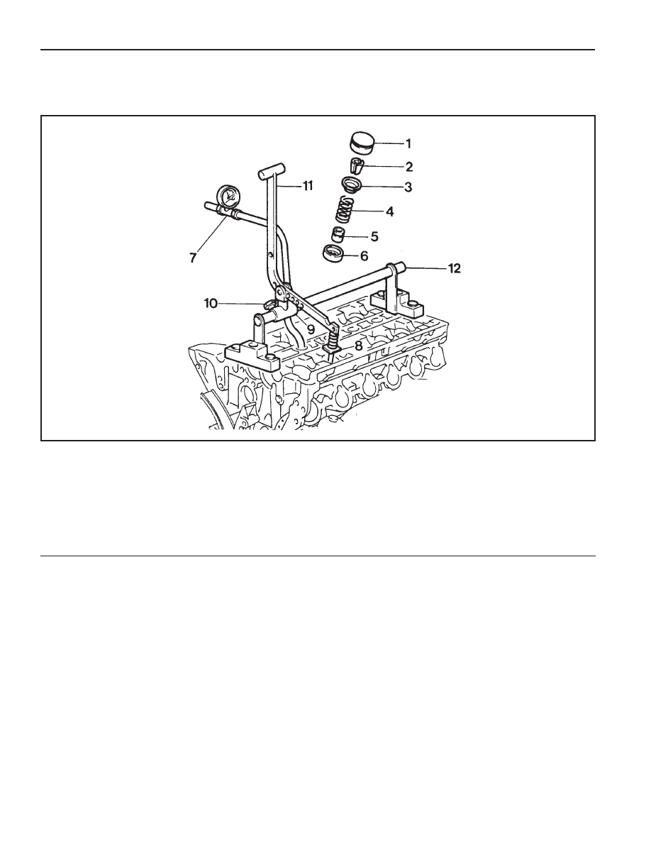
VALVE SPRING
Preceding Work : Removal of camshaft
Removal of spark plug
1 Valve Tappet Assembly
2 Valve Cotter
3 Upper Retainer
4 Valve Spring . . .. Check, Replace if necessary
5 Valve Stem Seal
6 Lower Retainer
7 Connecting Hose
8 Thrust Piece
9 Slide
10 Adjust Bolt
11 Lever Pusher
12 Supporting Bar

M161 ENGINE MECHANICAL 1B2-73
Tools Required
111 589 01 59 00
Supporting Bar
111 589 18 61 00
Lever Pusher
111 589 25 63 00
Thrust Piece
116 589 06 63 00 Magnetic Finger
Removal & Installation Procedure
1. Place the supporting bar (12) and the slide (9) at the
camshaft bearing cap (Nos 1 & 7/8&14) and tighten them
with the bearing cap bolt.
Installation Notice
2. Turn the crankshaft to position the each cylinder piston at
TDC.
5. Install the engine lock to the ring gear to prevent the
crankshaft from rotating.
6. Blow up with compressed air.
Notice
z
Remove the valve spring only at TDC.
z
Always rotate the crankshaft by holding the chain to
prevent from timing chain damage and tangling, and for
smooth rotation.
3. Remove the valve tappet (1) using the magnetic finger.
4. Install the leakage tester connecting hose to the spark plug
hole.
Supporting Bar 111 589 01 59 00
Tightening Torque
22.5 - 27.5 Nm
Mark on The Vibration Damper
OT
UT
Cylinder
1, 4
2, 3
1B2-74 M161 ENGINE MECHANICAL
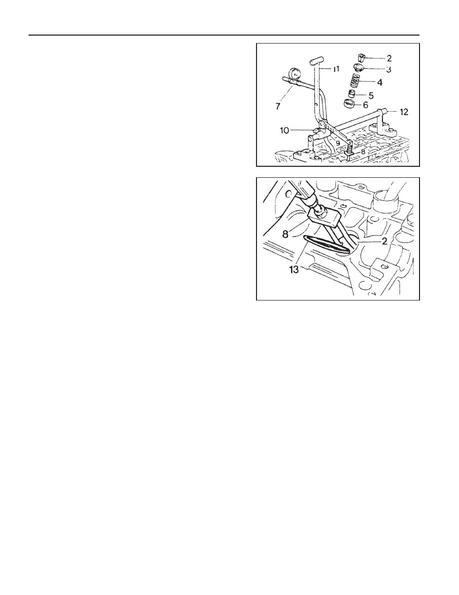
8. Install the lever pusher (11) and the thrust piece (8) to the
slide (9).
13. Remove the valve cotter (2) using either the pincette (13)
or magnetic finger.
Lever Pusher 111 589 18 61 00
Magnetic Finger 116 589 06 63 00
9. Mount the thrust piece (8) vertically to the valve spring
retainer (3).
10. Make the thrust piece (8) and the slide (9) perpendicular
to each other.
11. Secure the slide (9) by turning the adjust bolt (10).
12. Press the valve spring (4) by using the lever pusher (11).
14. Remove the upper retainer (3) and the valve spring (4).
15. Remove the valve stem seal and replace if necessary.
Notice
Check the valve stem seal and replace if necessary.
16. Remove the lower retainer (6).
Notice
Check the retainer for damages and replace with a new
one if necessary.
17. Installation should follow the removal procedure in the
reverse order.
Нет комментариевНе стесняйтесь поделиться с нами вашим ценным мнением.
Текст