SsangYong Musso. Manual — part 526
TRANSFER CASE (TOD) 5D2-51
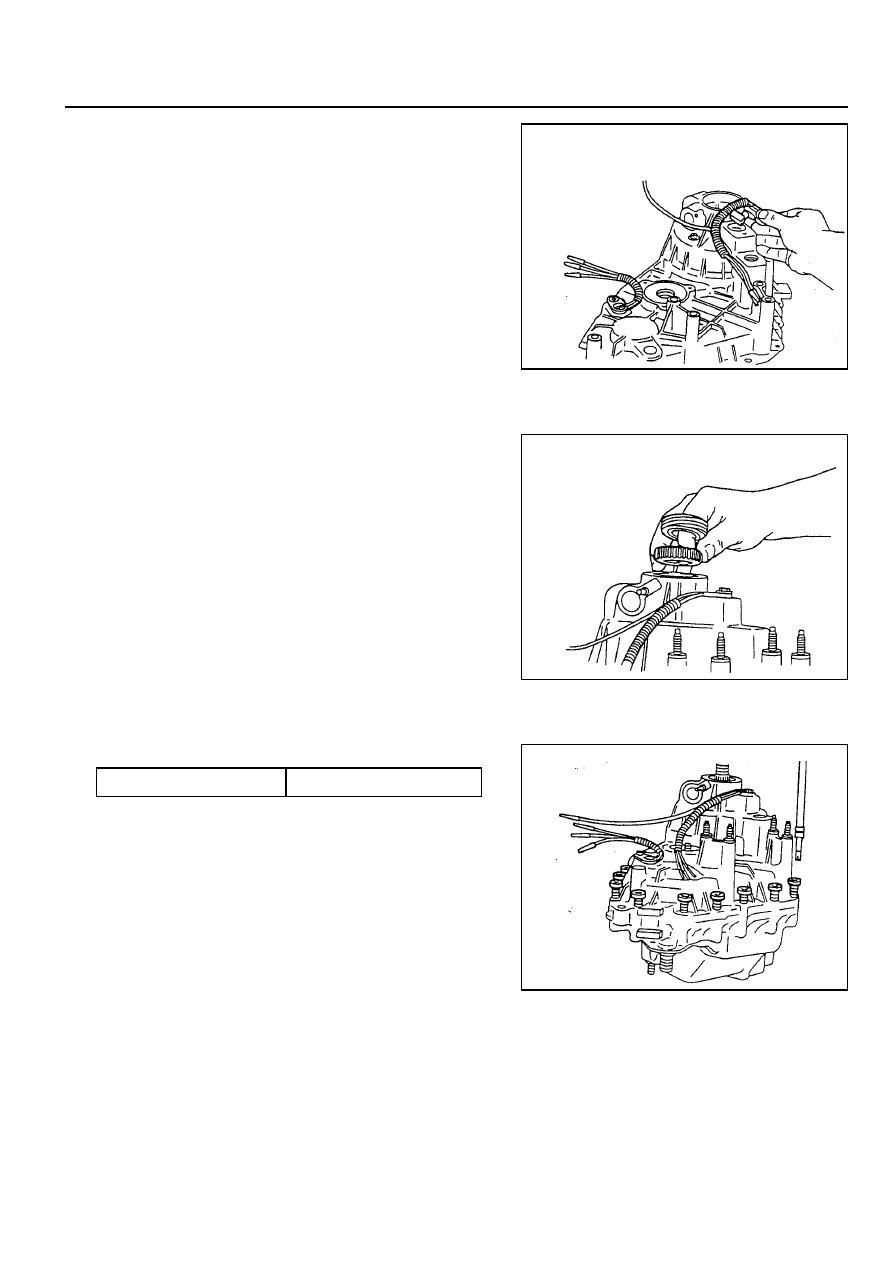
25. Install the pin on the tang end of the helical cam into the
hole in the front case. Position the torsion spring tangs so
that they are pointing toward the top side of the transfer
case and just touching the high-low shift fork.
CAUTION
Do not bend the helical cam during installation to the front
case because of possible damage to the pin at the tang
end of the motor shaft.
26. Install the shift rail through the high-low shift fork and make
sure that the reverse gear shift rail is seated in the front
case bore.
27. Install upper and lower speed sensors into the cover. Feed
the coil wire through the upper speed sensor wire shield.
28. Install upper tone wheel, speedometer gear and rear output
seal. Use Output Shaft Seal Replacer and Driver or
equivalent to install seal.
29. Coat the mating surface of the front case with a bead of
Black Non-Acid Cure Silicone Rubber or equivalent.
30. The following procedure must be followed prior to installing
the rear case onto the front case half:
a. Align the output shaft with the rear case output shaft bore.
b. Align the helical cam with the rear case motor bore.
If difficulty is encountered with seating the rear case, tap
the rear output shaft with a sharp blow using a rubber
mallet in a direction away from the triangular shaft while
pushing down on the rear case.
Tightening Torque
25 - 37 Nm
31. Install the bolts retaining the case halves and tighten.

5D2-52 TRANSFER CASE (TOD)
32. Install shift shaft oil seal if it is not installed.
33. Using pliers equipped with soft jaws, rotate the triangular
shaft so it is aligned with the triangular slot in the transfer
case shift motor. If triangular shaft will not rotate, rotate
the rear output shaft.
34. Slightly loosen the two nuts that attach the slotted support
bracket to the end of the motor house.
35. Apply Black Non-Acid Cure Silicone Rubber or equivalent
to motor housing base and install on transfer case.
36. Install the transfer case shift motor and three bolts along
with speed sensor wire harness bracket and tighten.
Notice
The wire harness must be routed as shown to provide
clearance and to prevent the wire harness from grounding
the damper.
37. Holding the slotted support bracket tight against the motor
housing end, secure the bracket to the transfer case,
tightening the bolt with lockwasher to 8-11 Nm (72-96 lb-
in).
38. Retighten the two nuts that attach the slotted support
bracket to the end of the motor.
39. Install the clutch coil wire terminal and sensor wires.

TRANSFER CASE (TOD) 5D2-53
40. Install the rear case flange on the output shaft. Install the
rubber seal, output shaft yoke washer and nut. Tighten
the nut.
Tightening Torque
137 - 196 Nm
41. Install the drainplug and tighten.
42. Fill the transfer case with 1.4 liters of Automatic
Transmission Fluid or equivalent.
Notice
Fluid level should be just below the filler plug hole.
Tightening Torque
19 - 30 Nm
Tightening Torque
19 - 30 Nm
43. Install the fill pulg and tighten.
44. Install the transfer case as outlined in removal and
Installation, transfer case in the section.
Notice
Make sure proper drain and fill plugs are installed if case
is replaced.

Application
Steering Wheel
Steering Gear Box
Oil Pump
Steering Column
Minmum Turning Radius
Oil
SECTION 6A
POWER STEERING SYSTEM
TABLE OF CONTENTS
Specifications . . . . . . . . . . . . . . . . . . . . . . . . 6A-1
General Specifications . . . . . . . . . . . . . . . . . . 6A-1
Fastener Tightening Specifications . . . . . . . . . 6A-1
Diagnosis . . . . . . . . . . . . . . . . . . . . . . . . . . . 6A-2
Hard Steering . . . . . . . . . . . . . . . . . . . . . . . . . 6A-2
Steering Pulls to One Side . . . . . . . . . . . . . . . 6A-2
Excessive Wheel Play . . . . . . . . . . . . . . . . . . . 6A-2
Poor Return of Steering Wheel . . . . . . . . . . . . 6A-2
Steering Wheel Shimmy . . . . . . . . . . . . . . . . . 6A-3
SPECIFICATIONS
GENERAL SPECIFICATIONS
Abnormal Noise From Steering System . . . . . 6A-3
Component Locator . . . . . . . . . . . . . . . . . . . 6A-4
Steering System . . . . . . . . . . . . . . . . . . . . . . . 6A-4
Maintenance and Repair . . . . . . . . . . . . . . . 6A-5
On-Vehicle Service . . . . . . . . . . . . . . . . . . . . . 6A-5
Inspection . . . . . . . . . . . . . . . . . . . . . . . . . . . . 6A-5
Oil Pump Pressure Check . . . . . . . . . . . . . . . . 6A-6
Bleeding of Power Steering System . . . . . . . . 6A-6
Steering Gear Box . . . . . . . . . . . . . . . . . . . . . 6A-7
Number of Spoke
Outer Diameter
Type
Gear Ratio
Inner Steering Angle
Outer Steering Angle
Type
Maximum Pressure
Upper Tilting Angle
Lower Tilting Angle
Type
Capacity
Change Interval
Description
4
396 mm
Rack and Pinion
∞
33°37'
31°50'
Vane
75-82 kg/cm
2
4.646°
6.969°
5.25m
ATF DEXRON II
1 L
Every 24,000 km
FASTENER TIGHTENING SPECIFICATIONS
Application
Steering Shaft Bolt
Pressure Hose Bolt
Return Pipe Nut
Slotted Nut
Steering Gearbox Bolt
N
!
!
!
!
!
m
30 - 40
12 - 18
12 - 18
35 - 45
35 - 45
Нет комментариевНе стесняйтесь поделиться с нами вашим ценным мнением.
Текст