SsangYong Musso. Manual — part 165
1F-244 ENGINE CONTROLS
SSANGYONG Y158
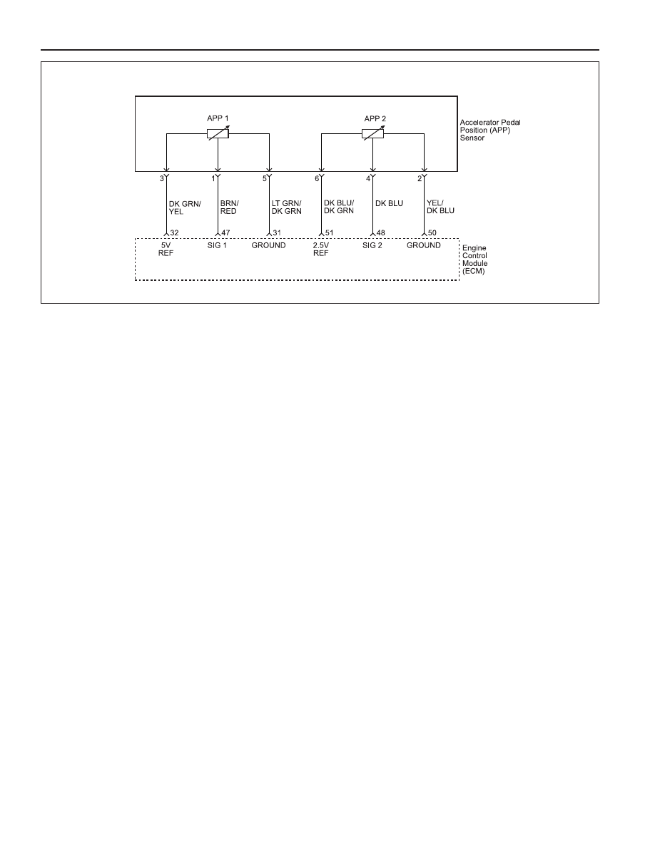
Circuit Description
The Engine Control Module (ECM) supplies a 5 or 2.5
volt reference signal and a ground to the Accelerator
Pedal Position sensor 1 or 2. The ECM calculates the
accelerator pedal position by monitoring the voltages
on these signal lines. The APP sensor output changes
as the accelerator pedal is moved. The outputs of the
APP sensor 1 and sensor 2 are low, about 0.4 - 0.7
volts and 0.2 - 0.35 volts respectively at the closed
throttle posi-tion. As pushing the accelerator pedal, the
output in-creases so that the output voltages will be
about 4.3 - 4.8 volts and 2.1 - 2.4 volts individually when
accelerating fully with the kickdown, at Wide Open
Throttle (WOT).
Conditions for Setting the DTC
•••••
Ignition ON.
•••••
Electrical system protection is not active.
Action Taken When the DTC Sets
•••••
The Malfunction Indicator Lamp (MIL) will illuminate
after two consecutive driving cycles in which the diag-
nostic runs with the fault active.
•••••
The ECM will record operating conditions at the time
the diagnostic fails. This information will be stored in
the Freeze Frame and Failure Records buffers.
•••••
A history DTC is stored.
Conditions for Clearing the MIL/DTC
•••••
The MIL will turn off after three consecutive driving
cycles in which the diagnostic runs without a fault.
•••••
A history DTC will clear after 40 consecutive warm-
up cycles without a fault.
•••••
The DTC(s) can be cleared using the scan tool.
DIAGNOSTIC TROUBLE CODE (DTC) P0220
ACCELERATOR PEDAL POSITION SENSOR MALFUNCTION
Diagnostic Aids
If a DTC P0220 cannot be duplicated, the information
included in the Freeze Frame data can be useful. Use
the scan tool information data to determine the status
of the DTC. If the DTC occurs intermittently, using the
Diagnostic table may help isolate the problem.
Test Description
Number(s) below refer to the step number(s) on the
Diagnostic Table.
1. The Euro On-Board Diagnostic (EOBD) System
Check prompts the technician to complete some
basic checks and store the freeze frame and failure
records data on the scan tool if applicable. This
creates an electronic copy of the data taken when
the malfunction occurred. The information is then
stored on the scan tool for later reference.
3. Normal APP 1 voltage when the throttle plates are
ful-ly closed is between 0.4 - 0.7 volts. A sensor
will display a higher voltage when the sensor is stuck
or a circuit is faulty.
4. Normal APP 2 voltage when the throttle plates are
fully closed is between 0.2 - 0.35 volts. A sensor
will display a higher voltage when the sensor is stuck
or a circuit is faulty.
5. If DTC P0220 cannot be duplicated, the information
included in the Freeze Frame / Failure Records data
can be useful. Use the scan tool DTC information
data to determine the status of the DTC.
6. A disconnected APP sensor should not display a
voltage reading on the scan tool. An amount less
than the specified value is normal.
YAA1F630

ENGINE CONTROLS 1F-245
SSANGYONG Y158
1
Perform an Euro On-Board Diagnostic (EOBD) System
Check.
Is the system check complete?
1. Turn the ignition switch ON, with the engine OFF.
2. Install a scan tool.
3. Select the Throttle Position (TP) angle parameter on
the scan tool.
4. Monitor the scan tool while pressing the accelerator
pedal to the floor and then slowly releasing the
pedal. (Repeat the procedure several times.)
Does the TP angle value increase steadily when the
accelerator pedal is pressed to greater than the
specified value and decrease steadily when the pedal is
released to less than the specified value?
Does the scan tool display a accelerator pedal position
(APP) sensor 1 voltage between the specified value
when the throttle is fully closed?
Does the scan tool display a accelerator pedal position
(APP) sensor 2 voltage between the specified value
when the throttle is fully closed?
1. Review the Freeze Frame data and note the
parameters.
2. Operate the vehicle within the Freeze Frame
conditions and Conditions for Setting The DTC as
noted.
Is the DTC P0220 set again?
1. Turn the ignition OFF.
2. Disconnect the APP sensor electrical connector.
3. Turn the ignition ON.
Is the APP sensor 1 or 2 voltage near the specified
value?
Check the APP sensor 1 signal circuit at the APP
sensor 1 harness connector terminal 1 for a short to
voltage and repair as necessary.
Is a repair necessary?
Check the APP sensor 2 signal circuit at the APP
sensor 2 harness connector terminal 4 for a short to
voltage and repair as necessary.
Is a repair necessary?
Step
Action
Value(s)
Yes
No
DTC P0220 Accelerator Pedal Position Sensor Malfunction
-
Go to Step 2
Go to “Euro
On-Board
Diagnostic
System Check”
2
3
0.2 - 0.35 v
Go to Step 5
Go to Step 6
4
20. The replacement ECM must be reprogrammed. Re-
fer to the latest Techline procedure for ECM repro-
gramming.
22. If no faults have been found at this point and no
additional DTCs were set, refer to “Diagnostic Aids”
in this section for additional checks and information.
0.4 - 0.7 v
Go to Step 4
Go to Step 6
-
Go to Step 6
Go to Step 25
-
Go to Step 25
Go to Step 24
-
Go to Step 25
Go to Step 24
5
6
7
8
98 %
1 %
Go to Step 3
Go to Step 5
0 v
0 v
Go to Step 9
If APP1 value is
more than
specified value,
Go to Step 7
If APP2 value is
more than
specified value,
Go to Step 8

1F-246 ENGINE CONTROLS
SSANGYONG Y158
9
Jumper the 5 volt reference circuit, terminal 3 and the
APP sensor 1 signal circuit, terminal 1 together at the
APP sensor electrical connector.
Is the APP sensor 1 voltage over the specified value?
Jumper the 2.5 volt reference circuit, terminal 6 and the
APP sensor 2 signal circuit, terminal 4 together at the
APP sensor electrical connector.
Is the APP sensor 2 voltage over the specified value?
Connect a test light between B+ and the APP sensor 1
signal circuit at terminal 1.
Is the APP sensor 1 voltage greater than the specified
value?
Check the 5 volt reference circuit for an open or short to
ground and repair as necessary.
Check the 5 volt reference circuit for a poor connection
at the Engine Control Module (ECM), terminal 32 and
repair the terminal as necessary.
Is the repair complete?
Check the APP sensor 1 signal circuit, terminal 3 for an
open or short to ground and repair as necessary.
Is the repair complete?
Connect a test light between B+ and the APP sensor 2
signal circuit at terminal 4.
Is the APP sensor 2 voltage greater than the specified
value?
Check the 2.5 volt reference circuit for an open or short
to ground and repair as necessary.
Check the 2.5 volt reference circuit for a poor
connection at the Engine Control Module (ECM),
terminal 51 and repair the terminal as necessary.
Is the repair complete?
Check the APP sensor 2 signal circuit, terminal 4 for an
open or short to ground and repair as necessary.
Is the repair complete?
Connect a test light to B+ and probe the ground circuit
at terminal 5 of the APP sensor 1 harness connector.
Does the test light illuminate?
Connect a test light to B+ and probe the ground circuit
at terminal 2 of the APP sensor 2 harness connector.
Does the test light illuminate?
Check the APP sensor 1 ground circuit , terminal 5 for
open and repair as necessary?
Is the repair complete?
Check the APP sensor 2 ground circuit , terminal 2 for
open and repair as necessary?
Is the repair complete?
Step
Action
Value(s)
Yes
No
DTC P0220 Accelerator Pedal Position Sensor Malfunction (Cont'd)
4.0 v
Go to Step 10
Go to Step 11
2.0 v
Go to Step 19
Go to Step 15
10
11
4.0 v
Go to Step 12
Go to Step 14
-
Go to Step 25
Go to Step 24
13
-
Go to Step 25
Go to Step 24
14
-
Go to Step 25
Go to Step 13
12
2.0 v
Go to Step 16
Go to Step 18
15
-
Go to Step 17
Go to Step 17
16
-
Go to Step 25
Go to Step 24
17
-
Go to Step 25
Go to Step 24
18
-
Go to Step 20
Go to Step 21
19
-
Go to Step 23
Go to Step 22
20
-
Go to Step 25
Go to Step 24
21
22
-
Go to Step 25
Go to Step 24

ENGINE CONTROLS 1F-247
SSANGYONG Y158
23
Step
Action
Value(s)
Yes
No
24
25
26
1. Turn the ignition OFF.
2. Replace the APP sensor.
Is the action complete?
1. Turn the ignition OFF.
2. Replace the ECM.
Is the repair complete?
1. Using the scan tool, clear the Diagnostic Trouble
Codes (DTCs).
2. Start the engine and idle at normal operating
temperature.
3. Operate the vehicle within the conditions for setting
this DTC as specified in the supporting text.
Does the scan tool indicate that this diagnostic ran and
passed?
Check if any additional DTCs are set.
Are any DTCs displayed that have not been diagnosed?
-
Go to Step 25
-
-
Go to Step 25
-
-
Go to Step 26
Go to Step 2
DTC P0220 Accelerator Pedal Position Sensor Malfunction (Cont'd)
-
Go to
applicable
DTC table
System OK
Нет комментариевНе стесняйтесь поделиться с нами вашим ценным мнением.
Текст