SsangYong Musso. Manual — part 215
1F-444 ENGINE CONTROLS
SSANGYONG Y158
ENGINE DATA DISPLAY TABLE
DEFINITION
ECM Data Description
The following information will assist in diagnosing emis-
sion or drivability problems. A first technician can view
the displays while the vehicle is being driven by second
technician. Refer to Euro On-Board Diagnostic (EOBD)
System Check for additional information.
Accel. Pedal Position
This sensor works with the TP sensor to provide input
to the ECM regarding driver requested accelerator pedal
and throttle angle at the throttle body.
A/C S/W Condition
The A/C Relay represents the commanded state of the
A/C clutch control relay. The A/C clutch should be en-
gaged when the scan tool displays ON.
Engine Coolant Temperature
The Engine Coolant Temperature (ECT) sensor sends
engine temperature information to the ECM. The ECM
supplies 5 volts to the engine coolant temperature sen-
sor circuit. The sensor is a thermistor which changes
in-ternal resistance as temperature changes. When the
sensor is cold (internal resistance high), the ECM moni-
tors a high voltage which it interprets as a cold engine.
As the sensor warms (internal resistance decreases),
the voltage signal will decrease and the ECM will inter-
pret the lower voltage as a warm engine.
Engine Load
Indicates engine load based on manifold absolute pres-
sure. The higher the percentage, the more load the en-
gine is under.
Engine RPM
Engine RPM is computed by the ECM from the fuel
control reference input. It should remain close to desired
idle under the various engine loads with the engine id-
ling.
Fuel Integrator
The fuel integrator is derived from the short term fuel
trim value. The fuel integrator is used for the long term
correction of the fuel delivery. A value of 1 (0%) indicates
that the fuel delivery requires no compensation in order
to maintain a 14.7:1 air to fuel ratio. A value below 1
means that the fuel system is too rich and the fuel
delivery is being reduced. The ECM is decreasing the
injector pulse width. A value above 1 indicates that a
l e a n c o n d i t i o n e x i s t s f o r w h i c h t h e E C M i s
compensating.
Injection Time
Indicates the base Pulse Width Modulation (PWM) or
ON time of the indicated cylinder injector in milliseconds.
When the engine load is increased, the injector pulse
width will increase.
Intake Air Temperature
The ECM converts the resistance of the Intake Air Tem-
perature (IAT) sensor to degrees in the same manner as
the Engine Coolant Temperature (ECT) sensor. Intake
air temperature is used by the ECM to adjust fuel delivery
and spark timing according to incoming air density.
Mass Air Flow
Hot film air flow sensor detects the air mass supplied to
the engine and intake temperature. The air mass sup-
plied to the engine flows through the mass air flow sen-
sor in the air intake port and thus influence at the hot
film sensor. At the same time, the intake air temperature
is detected by an integrated NTC resistor.
Misfire Count for catalyst damage #1-6
Indicates the number of current misfires that are present
in the indicated cylinder. Increments only when misfire
is current.
Oxygen Sensor
The pre-converter Oxygen Sensor (O2S 1and O2S 3)
reading represents the exhaust oxygen sensor output
voltage. This voltage will fluctuate constantly between
100 mv (lean exhaust) and 900 mv (rich exhaust) when
the system is operating in a Closed Loop.
The post-converter Heated Oxygen Sensor (O2S 2 and
O2S 4) represents the exhaust oxygen output voltage
past the catalytic converter. This voltage remains
inactive, or the voltage will appear lazy within a range of
100 mv (lean exhaust) and 900 mV (rich exhaust) when
operating in a Closed Loop.
Purge Control Valve
The purge control valve is activated by the ECM fre-
quency according with the engine rotating speed to ad-
just the purification rate. The purification rate is
determined by the continuous solenoid opening interval.
Regular RPM
The ECM commands the idle speed. The ECM compen-
sates for various engine loads in order to maintain the
desired idle speed. The actual engine speed should re-
main close to the desired idle under the various engine
loads with the engine idling.
Spark Advance
This is a display of the spark advance lgnition Coil
calculation which the ECM is programming in the ignition
system. It computes the desired spark advance using
data such as engine temperature, rpm, engine load,
vehicle speed and operating mode.
ENGINE CONTROLS 1F-445
SSANGYONG Y158
FUEL SYSTEM SPECIFICATION
Use Only Unleaded Fuel Rated at 89 Octane
or Higher
Fuel quality and additives contained in fuel have a signifi-
cant effect on power output, drivability, and life of the
engine. Fuel with too low an octane number can cause
engine knock.
Caution: Use of fuel with an octane number lower
than 89 may damage engine and exhaust system.
Notice: To prevent accidental use of leaded fuel, the
nozzles for leaded fuel are larger, and will not fit the fuel
filler neck of your vehicle.
Do Not Use Methanol
Fuels containing methanol (wood alcohol) should not
be used in vehicle.
This type of fuel can reduce vehicle performance and
damage components of the fuel system.
Caution: Use of methanol may damage the fuel sys-
tem.
Vehicle Fueling from Drums or Storage
Containers
For safety reasons (particularly when using noncom-
mercial fueling systems) fuel containers, pumps and
hoses must be properly earthed.
Static electricity build up can occur under certain atmo-
spheric and fuel flow conditions if unearthed hoses, par-
ticularly plastic, are fitted to the fuel-dispensing pump.
It is therefore recommended that earthed pumps with
in-tegrally earthed hoses be used, and that storage con-
tainers be properly earthed during all noncommercial
fueling operations.
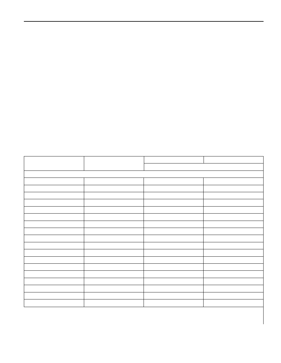
Temperature Vs Resistance
°C
°F
ECT sensor
IAT sensor
OHMS (
Ω
)
130
120
110
100
90
80
70
60
50
40
30
20
10
0
-10
-20
-30
-40
266
248
230
212
194
176
158
140
122
113
86
68
50
32
14
-4
-22
-40
88
111.6
143
202
261
340
452
609
835
1166
1662
2420
3604
5499
8609
13850
22960
39260
102
127
159
202
261
340
452
609
835
1166
1662
2420
3604
5499
8609
13850
22960
39260
Temperature vs Resistance Values (Approximate)

1F-446 ENGINE CONTROLS
SSANGYONG Y158
ECM WIRING DIAGRAM (2.3L DOHC - 1 OF 7) (MSE 3.53D)
SCHEMATIC AND ROUTING DIAGRAMS
YAA1F010

ENGINE CONTROLS 1F-447
SSANGYONG Y158
ECM WIRING DIAGRAM (2.3L DOHC - 2 OF 7) (MSE 3.53D)
Y
AA1F090
Нет комментариевНе стесняйтесь поделиться с нами вашим ценным мнением.
Текст