SsangYong Musso. Manual — part 307

1E1-10 M162 ENGINE ELECTRICAL
Functions
1. Firing order : 1-5-3-6-2-4
2. The ignition cables are located on the cylinder head cover.
Each ignition coil provides the high voltage to two spark
plugs simultaneously.
-
T1/1 : cylinder 2 and 5
-
T1/2 : cylinder 3 and 4
-
T1/3 : cylinder 1 and 6
Removal & Installation Procedure
1. Disconnect the negative battery cable (1).
2. Remove the ignition cable connector from the ignition cable.
3. Disconnect the secondary spark plug connectors from the
each spark plugs and remove the ignition cable.
Installation Notice
3. The secondary output voltage (5a) is supplied to the No.2
cylinder spark plug through the spark plug connector. The
secondary output voltage (5b) is supplied to the No.5 cylinder
spark plug through the ignition cable. The guide pin (W)
acts as a ground while the ignition cable is operated.
!
Make sure that the ignition cables are correctly routed.
!
Exactly install the ignition cable guide pin into the vehicle
to be grounded.
4. Installation should follow the removal procedure in the
reverse order.
Tightening Torque
9 - 11 Nm
M162 ENGINE ELECTRICAL 1E1-11
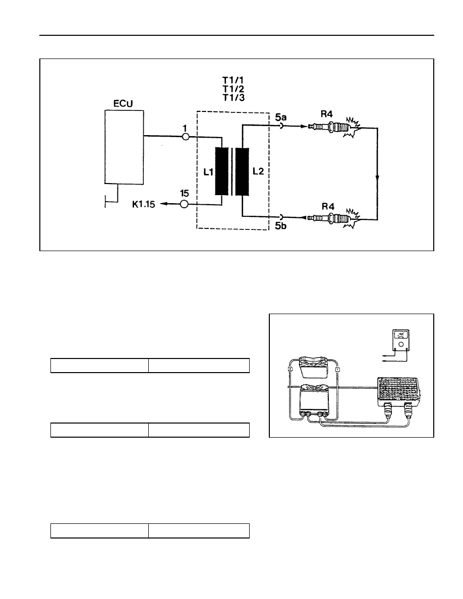
Circuit Diagram
Inspection & Maintenance Procedure (for MSE)
1. While the ignition switch is in 'OFF' position, remove the
wiring connectors (1 and 15) from ignition coil and measure
the primary resistance between terminal No.1 and No.15.
2. During engine cranking, measure primary voltage (T1/1)
between ECU terminal No. 71 and No. 69.
Notice
If out of specified value, replace the ignition coil.
Specified Value
0.9 - 1.6
Ω
(20°C)
Specified Value
200 - 350 V
Notice
!
Measure remaining cables.
- T1/2 : No. 72 and 69.
- T1/3 : No. 70 and 69.
!
If out of specified value, check ignition cable and ECU.
3. Using a multi-tester, measure the secondary coil resistance
between 5a and 5b.
Specified Value
6 - 8.5 k
Ω
1E1-12 M162 ENGINE ELECTRICAL
UNIT REPAIR
BATTERY
Inspection
Notice
!
When charging the battery, do not leave the inflammable
objects around it.
!
When checking the electrolyte of battery, put on
an eye protector and gloves.
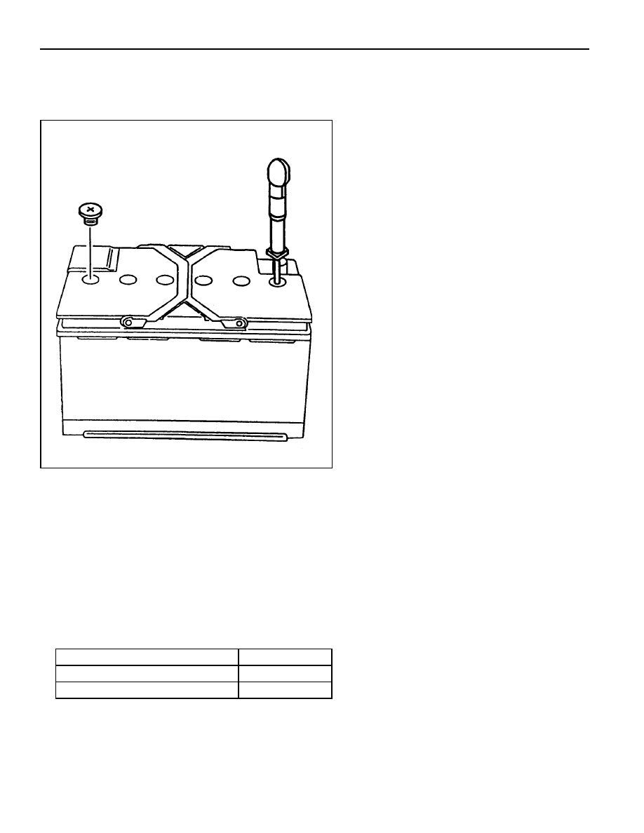
1. Inspect the surface of the battery and replace if any defects
were found on it.
2. Check if the specific gravity of the electrolyte is within the
specified value.
Notice
!
Replace the battery if the maximum tolerance of the
electrolyte between cells is out of the specified value.
!
Measure the specific gravity in the approx. 20°C
of ambient temperature.
3. Replenish the electrolyte if necessary.
Battery capacity(Ah)
Battery specific gravity
Max. tolerance between cells
85
≥
1.24
≥
0.04

SECTION 1E2
M161 ENGINE ELECTRICAL
Specifications . . . . . . . . . . . . . . . . . . . . . . . 1E2-1
Alternator Specifications . . . . . . . . . . . . . . . . 1E2-1
Starting Motor Specifications . . . . . . . . . . . . 1E2-2
Battery Specifications . . . . . . . . . . . . . . . . . . 1E2-2
Fastener Tightening Specifications . . . . . . . . 1E2-2
Special Tools . . . . . . . . . . . . . . . . . . . . . . . 1E2-3
Special Tools Table . . . . . . . . . . . . . . . . . . . . 1E2-3
Maintenance and Repair . . . . . . . . . . . . . . 1E2-4
On-Vehicle Service . . . . . . . . . . . . . . . . . . . . . 1E2-4
Alternator . . . . . . . . . . . . . . . . . . . . . . . . . . . 1E2-4
Starting Motor . . . . . . . . . . . . . . . . . . . . . . . . 1E2-5
Battery . . . . . . . . . . . . . . . . . . . . . . . . . . . . . 1E2-6
Spark Plug . . . . . . . . . . . . . . . . . . . . . . . . . . 1E2-7
Ignition Cable . . . . . . . . . . . . . . . . . . . . . . . . 1E2-9
Unit Repair . . . . . . . . . . . . . . . . . . . . . . . . 1E2-12
Battery . . . . . . . . . . . . . . . . . . . . . . . . . . . . 1E2-12
CAUTION: Disconnect the negative battery cable before removing or installing any electrical unit or when a
tool or equipment could easily come in contact with exposed electrical terminals. Disconnecting this cable
will help prevent personal injury and damage to the vehicle. The ignition must also be in LOCK unless otherwise
noted.
TABLE OF CONTENTS
SPECIFICATIONS
ALTERNATOR SPECIFICATIONS
Application
Output Voltage
Current
Resistance Between Rotor Core and Slip Ring
Description
12 - 14 V
115 A
∞ Ω
Нет комментариевНе стесняйтесь поделиться с нами вашим ценным мнением.
Текст