SsangYong Musso. Manual — part 431
3D-10 REAR DRIVE AXLE
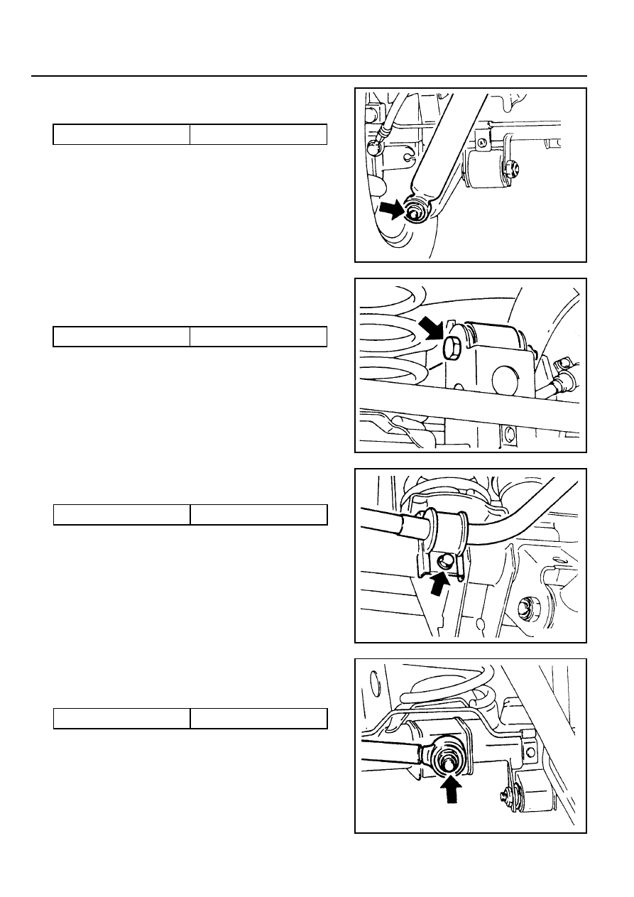
6. Separate the lower shock absorber from the axle housing.
Installation Notice
7. Remove the upper arm mounting nuts and remove the
upper arm form the axle housing.
Installation Notice
Tightening Torque
50 - 65 Nm
8. Remove the stabilizer bar.
Installation Notice
Tightening Torque
150 - 180 Nm
9. Remove the lateral rod mounting nuts and remove the
lateral rod from the axle housing.
Installation Notice
Tightening Torque
30 - 45 Nm
10. Lowering the axle housing slowly, remove the coil springs
and spring seats.
11. Installation should follow the removal precedure in the
reverse order.
Tightening Torque
150 - 180 Nm
REAR DRIVE AXLE 3D-11
UNIT REPAIR
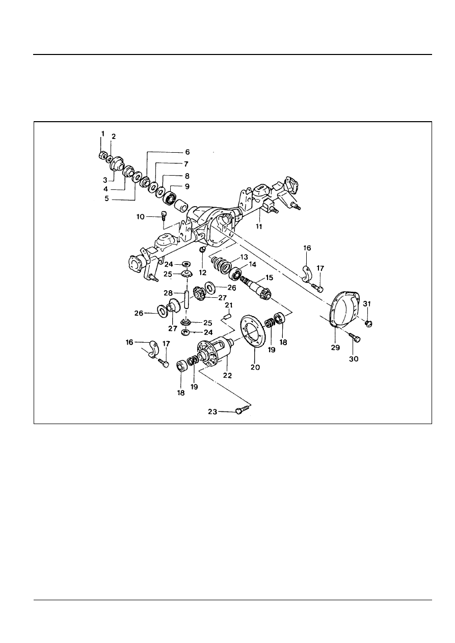
AXLE HOUSING
Preceding Work : Removal of the axle shaft
Removal of the axle housing
1 Drive Pinion Lock Nut . . . . . .. 240-310 Nm
2 Washer
3 Companion Flange
4 Pinion Oil Seal
5 Bearing Slinger
6 Bearing
7 Shim
8 Shim
9 Bearing Cup
10 Breather Nipple
11 Rear Axle Housing
12 Oil Drain Plug . . . . . . . . . ... 28-42 Nm
13 Shim
14 Bearing
15 Drive Pinion
16 Bearing Cap
17 Bolt . . . . . . . . . . . . . 87-124 Nm
18 Bearing
19 Shim
20 Ring Gear
21 Shaft Lock Pin
22 Differential Case
23 Ring Gear Mounting Bolt . . . . . .. 75-90 Nm
24 Thrust Washer
25 Differential Pinion
26 Thrust Washer
27 Side Gear
28 Differential Shaft
29 Housing Cover
30 Bolt . . . . . . . . . . . . . .. 38-46 Nm
31 Oil Filler Plug . . . . . . . . . ... 28-42 Nm
3D-12 REAR DRIVE AXLE
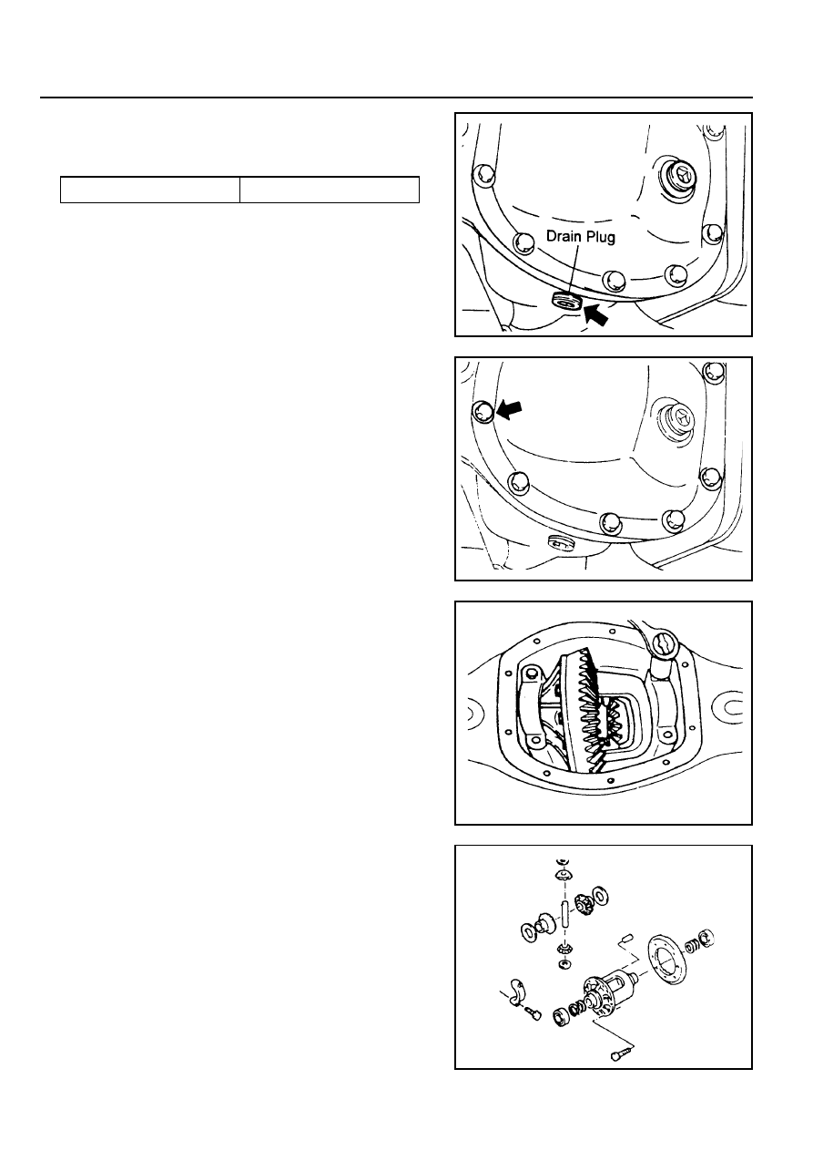
Disassembly Procedure
1. Remove the drain plug and drain the oil. Reinstall the drain
plug.
2. Remove the axle housing cover.
Notice
Clean the cover and housing contact surface.
3. Remove the bearing cap bolts and remove the bearing caps.
Pull out the differential carrier assembly.
Notice
Place alignment marks on the bearing cap not to change
the caps before removal. When pulling out the differential
carrier assembly, be careful not to damage the axle housing.
4. Disassemble the parts of the differential carrier assembly.
Tightening Torque
28 - 42Nm
REAR DRIVE AXLE 3D-13
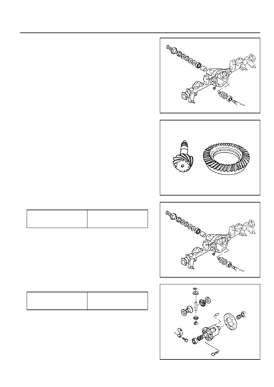
5. Remove the drive pinion lock nut. Disassemble the parts of
the drive pinion.
Assembly Procedure
1. Clean the all parts and check the followings.
!
Check the ring gear and drive pinion for wear or damage.
If damaged, replace it as set.
!
Check the bearing for sticks, wear, noise or turning
resistance.
!
Check the side gear, pinion, pinion shaft and thrust
washer for wear or damage.
!
Check the differential carrier for crack or wear (bearing
contact surface). Check the gear case for crack.
2. Assemble the parts of the drive pinion.
3. Assemble the parts of the differential carrier.
Tightening Torque of The
Pinion Lock Nut
240 - 310 Nm
Tightening Torque of The
Ring Gear Bolts
75 - 90 Nm
Нет комментариевНе стесняйтесь поделиться с нами вашим ценным мнением.
Текст