SsangYong Musso. Manual — part 347

M161 ENGINE CONTROLS 1F2-67
Crankshaft Position Sensor Resistance
Inspection
1. Disconnect the coupling "E" of ECU while the ignition switch
is in "OFF" position.
2. Measure the resistance between the coupling terminal pin
No.99 and No.100 using a multimeter.
Notice
Measure the insulator resistance of the crankshaft position
sensor if out of the specified value.
Crankshaft Position Sensor Output Wave
Inspection
1. Connect the test box to the ECU.
2. Measure the output wave between the ECU terminals No.99
and No.100 using the scanner or the oscilloscope while
engine cranking (starter motor activated).
Notice
Check the segment or crankshaft position sensor and air
gap if cannot get the output wave as shown in the figure.
Specified Value
1050 - 1400
Ω
Specified Value
> 20k
Ω
Crankshaft Position Sensor Insulator Resistance
Inspection
1. Disconnect the engine coupling from ECU while the ignition
switch is in "OFF" position.
2. Measure the resistance between the coupling terminal pin
No.100 and No.69.
Notice
Measure the check and ground terminal of the crankshaft
position sensor if out of the specified value.
1F2-68 M161 ENGINE CONTROLS
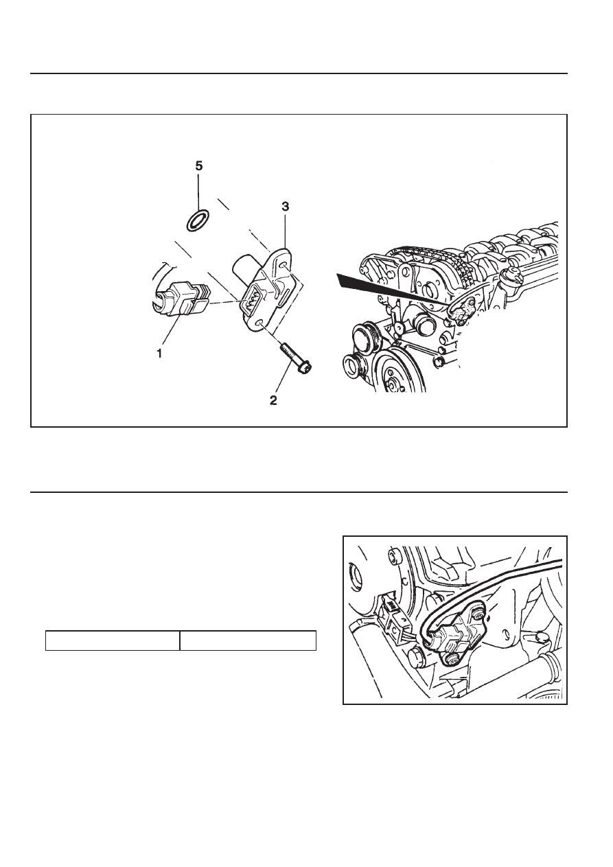
CAMSHAFT POSITION SENSOR
1 Bolt (M6 X 14) . . . . . . . . . . . 9-11Nm
2 Camshaft Position Sensor
Removal & Installation Procedure
1. Disconnect the wiring connector from the camshaft position
sensor.
2. Unscrew the bolt (2) and remove the camshaft position
sensor.
Installation Notice
3 Shim
5 O-ring
Tightening Torque
9 - 11 Nm
3. Check the clearance and replace the shim if necessary.
4. Check the O-ring for damage and replace it if necessary.
5. Installation should follow the removal procedure in the
reverse order.

M161 ENGINE CONTROLS 1F2-69
Camshaft Position Sensor Power Supply
Inspection
1. Turn the ignition switch to 'ON' position.
2. Disconnect the camshaft position sensor connector.
3. Measure the voltage between the No.1 and No.3 pin of
camshaft position sensor while the ignition switch is in "ON"
position.
Notice
If the measured value is not within the specified value, check
the cable.
Notice
The signal voltage will be changed in the range of 1.2~1.7V.
Camshaft Position Sensor Output Wave
Inspection
1. Connect the test box to the ECU.
2. Measure the output wave between the ECU terminal No.104
and No.106 using the scanner or the oscilloscope while the
engine speed is at idle.
Notice
Replace the camshaft position sensor if cannot get the
output wave as shown in the figure.
Specified Value
11 - 14 V
Specified Value
1.2 - 1.7 V
Camshaft Position Sensor Signal Voltage
Inspection
1. Connect the test box to the ECU.
2. Measure the voltage between the ECU terminal No.11 and
No.106 while the engine speed is at idle.
1F2-70 M161 ENGINE CONTROLS
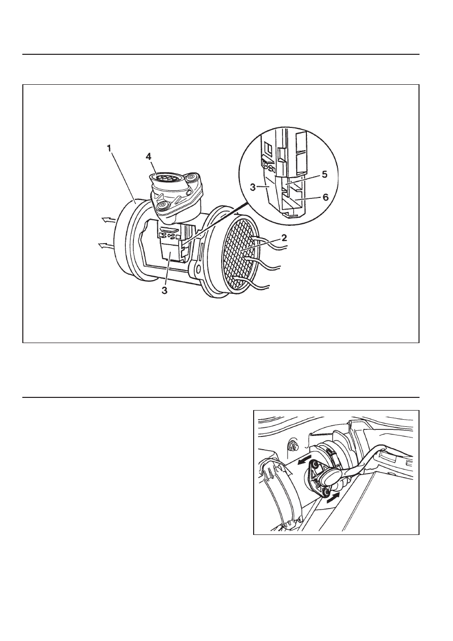
HOT FILM AIR MASS (HFM) SENSOR
1 Housing
2 Protector Net
3 Electronic Housing
Removal & Installation Procedure
1. Turn the HFM sensor coupling in the direction shown in the
figure in the right so that it gets separated from the contact
surface.
Notice
Make sure the HFM sensor coupling connects completely
with the contact surface Installation.
2. Remove the clip with a screw driver.
3. Pry off two tensioning clamps.
4. Remove the HFM sensor.
5. Installation should follow the removal procedure in the
reverse order.
4 Connector
5 Hot film Sensor
6 Measuring Port
Нет комментариевНе стесняйтесь поделиться с нами вашим ценным мнением.
Текст