SsangYong Musso. Manual — part 477
AUTOMATIC TRANSMISSION 5A-85
UNIT REPAIR
REBUILD WARNINGS
Prior to rebuilding a transmission system, the following warnings
are to be noted.
!
Ensure that, before replacing a transmission the cooler
lines are flushed out to remove any debris. This can be
done by applying compressed air to the rear cooler line
forcing oil and any contaminants out of the front cooler
line.
!
The cooler flow should be checked after the transmission
has been fitted. With the front cooler line connected
and the rear line run into a suitable container, measure
the flow over 15 seconds with the vehicle idling in park.
!
The flow rate should exceed 1 liter in 15 seconds.
!
Be wary of any situation where water enters the
transmission. This may result in fluid foaming and leaking
through the breather.
!
Ensure that both earth straps (one at the batted terminal
and one on the vehicle body) are connected in the
vehicle before connecting the positive side of the
battery.
!
Follow the throttle position calibration procedure in
section 7 of this manual if the powertrain control module
transmission control unit (PCM/TCU) is swapped.
DISASSEMBLY PROCEDURE
Transmission
Notice
Remove the inhibitor switch before washing the transmission
in solvent or hot wash.
It is assumed that the transmission fluid has been drained
when the transmission was removed from the
vehicle and that the ‘special tools’ quoted are available.
The transmission is dismantled in a modular fashion, and the
details of disassembly for each module are given under the
appropriate subject. Refer to table 9.10 in section 9.6 for details
of all special tools required when performing disassembly
procedures.
Technicians overhauling these transmissions will also require
a selection of good quality Torx bit sockets, in particular
numbers 30, 40 and 50, and an 8 mm,10 mm and 12 mm
double hex socket.
To disassemble the transmission, proceed as follows:
1. Remove the converter and the converter housing.
2. Mount the transmission on the bench cradle
No.0555-331895.
3. Remove the sump and the sump seal.

5A-86 AUTOMATIC TRANSMISSION
9. Remove the pump to case bolts using a multi-hex 8 mm
spanner.
10. Using the pump puller No. 0555-332941, remove the pump.
11. Remove the input shaft, forward clutch cylinder, and the
overdrive shaft as an assembly, withdrawing them through
the front of the case.
12. Remove the C3 clutch cylinder and sun gears.
13. Remove the fronts band struts. Remove the front band.
14. Remove the two centre support retaining bolts using a
T50 Torx bit.
15. Remove the centre support retaining circlip.
Notice
Do not hammer the output shaft to remove the centre
support as this will cause permanent damage to the thrust
bearing surfaces.
16. Remove the centre support, 1-2 one way clutch, planetary
gear set and output shaft as an assembly.
17. Remove the parking rod cam plate. (T40 Torx bit).
18. Remove the rear band struts and remove the band.
4. Detach each end of the filter retaining clip from the valve
body and remove the filter.
5. Detach the wires from each solenoid and lay the wiring to
one side.
6. Remove the valve body securing screws and remove the
valve body from the case.
7. Remove the front servo cover circlip.
Remove the cover and piston.
Notice
The plastic servo block is retained by the piston return
spring only.
8. Where fitted, remove the flange yoke, and then remove
the extension housing (RWD model).
Remove the adaptor housing (4WD model).
AUTOMATIC TRANSMISSION 5A-87
Transmission Case
To teardown the transmission case, proceed as follows:
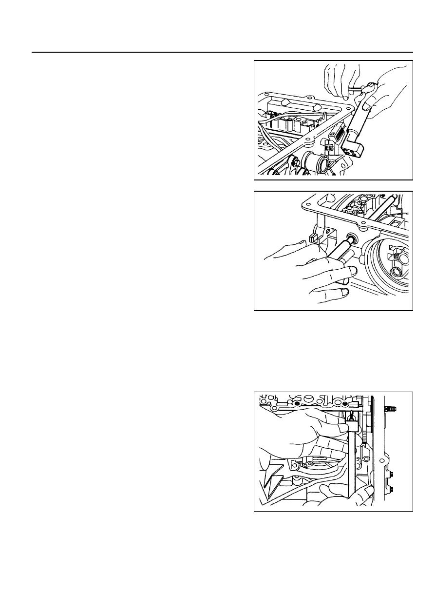
1. Remove the pin from the cross shaft inhibitor switch side
(4WD models) using tool No.0555-332942.
2. Remove the inhibitor switch from the case.
Remove the cross shaft seals with special tool No.0555-
331893.
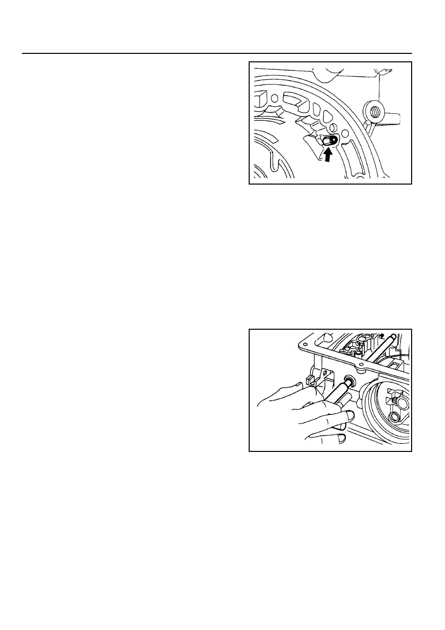
3. Remove the circlip from the cross-shaft. Pull the shaft to
release the drive pin from the selector quadrant.
4. Using tool No. 0555-331897, press the pin from the cross-
shaft and withdraw the shaft from the case. Retrieve the
spring and pin
5. Remove the manual valve lever and the park rod.
6. Remove the 10 pin plug from the wiring loom bracket
adjacent to the inhibitor switch(RWD models),
7. Depress the tangs and withdraw the 10 pin connector from
the case. Remove the loom assembly.
5A-88 AUTOMATIC TRANSMISSION
8. Detach the No.7 solenoid wire from the front of the case.
9. Remove the parking pawl pivot pin and the pawl and spring
from the case.
10. Remove the shaft and the rear servo lever.
11. Remove the rear servo cover and piston assembly.
12. Remove the B1R circlip, valve and spring.
13. Remove both band adjustment shims.
14. Inspect the output shaft bushing in the case and replace if
necessary.
15. Inspect cooler line fittings and replace as necessary.
16. Inspect the case for damage.
17. To remove the park rod lever: Remove the circlip from the
inner end of the pivot shaft and tap the outer end of the
shaft until it moves free from the case, then using a wide
shallow tapered drift as a wedge, drive the pin out from
the inside of the case and remove the lever and spring.
Notice
Do not remove the park rod lever unless absolutely
necessary.
Нет комментариевНе стесняйтесь поделиться с нами вашим ценным мнением.
Текст