SsangYong Musso. Manual — part 3
MUSSO-SPORTS 1A-9
SUPPLEMENT
Test Step 1: EGR operating range (between vacuum pump and EGR valve)
(Condition: at idling)
Remove the vacuum modulator 1
and vacuum line (to the direction
of vacuum pump), then install
vacuum tester.
Check whether the vacuum pressure
can be generated between vacuum
modulator 1 and vacuum line
(vacuum pump side).
Is the vacuum pressure of 900 mbar
generated?
Is the vacuum pressure properly
generated in the vacuum line
between vacuum modulator 1 and
EGR valve?
Check the EGR valve for leaks and
sticking.
Remove the vacuum hose from
outlet port (to the direction of vac-
uum pump) of vacuum modulator.
Connect the tester and check
whether vacuum pressure change
or not when the engine rpm
changes.
Install the tester into Inlet port of
EGR valve and check whether the
vacuum pressure changes or not
when engine rpm changes.
1. Start the engine, then remove EGR valve hose with idling. If the valve disk
snaps into position, EGR valve operates properly.
2. Install the T-connector into inlet port of EGR valve, then connects the manual
vacuum pump and the vacuum tester in each connection.
3. Generate -700 mbar of vacuum pressure with manual vacuum pump. If EGR
will not open (stay vacuum state), EGR valve should be replaced (due to
sticks of inner valve guide and valve).
Vacuum leaks from vacuum line
NO
Is the vacuum modulator 1 operated
properly?
•••••
Is the vacuum pressure varied
between 0 and 600 mbar?
•••••
Is the constant vacuum pressure
generated in constant engine speed?
Check the battery voltage can be
supplied to vacuum modulator 1
through EGR control unit. With the
battery voltage supplied, check the
vacuum pressure can be changed
according to the accelerator pedal
positions. If the vacuum pressure
cannot be generated or changed,
the vacuum modulator should be
replaced.
NO
Vacuum modulator 1 has a
problem in power supplying
system.
NO
Replace the vacuum line
between vacuum modulator 1
and EGR valve with new one.
YES
YES
YES

1A-10 MUSSO-SPORTS
SUPPLEMENT
Test Step 2: Exhaust gas control mode with no-load sharp acceleration (between vacuum pump and ALDA)
Condition:
1. At idling, monitor the changes
o f b o o s t p r e s s u r e w h i l e
changing the accelerator pedal
position slowly.
2. Remove the inlet port from
ALDA on fuel injection pump,
then install the pressure tester.
Before checking the generation of vacuum pressure, Check whether the boost
pressure from intake manifold can be applied to ALDA or not in the range beyond
no-load sharp acceleration mode.
Check whether the boost pressure
can be generated between intake
manifold and ALDA.
Boost pressure at idling: approx. 5 ~ 7
mbar.
While depressing the accelerator pedal
slowly, does the boost pressure of 220 ~
270 mbar generate at 4,000 ~ 4,500 rpm?
At idling, install the pressure tester
into inlet port of vacuum modulator
2 and read the negative pressure
(specified value: approx. -900
mbar) on tester.
Install the vacuum tester into inlet
port of solenoid valve, and check
whether the negative pressure is
generated in no-load sharp accel-
eration mode or not, and read the
changes of vacuum pressure
within specified ranges.
NO
If the boost pressure is not within
s p e c i f i e d v a l u e , a p p r o p r i a t e
pressure line should be replaced.
Check the solenoid valve with the
same method in no-load sharp
acceleration mode.
YES
YES
Check the vacuum circuit in no-load
sharp acceleration mode.
Is the approx. -900 mbar of negative
pressure generated between vacuum
pump line and inlet port of vacuum
modulator 2?
In vacuum modulator 2, check the
vacuum circuit between inlet port
and outlet port.
Is the approx. -300 ~ 650 mbar of
negative pressure generated in no-load
sharp acceleration mode?
Check the vacuum circuit between
outlet port of vacuum modulator 2
and inlet port of solenoid valve.
Is the approx. -300 ~ 650 mbar of
negative pressure generated in no-load
sharp acceleration mode?
Install the vacuum tester into outlet
port of vacuum modulator, and
c h e c k w h e t h e r t h e n e g a t i v e
pressure is generated or not in no-
load sharp acceleration mode.
Check the intake boost
pressure by ranges
•••••
Boost pressure line
between intake manifold
and solenoid valve
•••••
Boost pressure line
between ALDA and solenoid
outlet valve
NO
Check the voltage supplying
and vacuuming
Check whether the EGR control unit
can supply the battery voltage to
vacuum modulator 2. If can, in no-
load sharp acceleration mode,
check whether the negative pressure
may vary within specified ranges. If
there are not any vacuuming or if the
negative pressure will not be varied,
replace the modulator with new one.
YES
YES
NO
Replace the vacuum hose in
the range.
MUSSO-SPORTS 1A-11
SUPPLEMENT
Install the vacuum tester into out-
let port of solenoid valve, and
check whether the negative pres-
sure is generated in no-load sharp
acceleration mode or not, and read
the changes of vacuum pressure
within specified ranges.
YES
In solenoid valve, check whether
the vacuum pressure is generated
between inlet port and outlet port.
When the power is supplied, does the
solenoid valve close and the intake
boost pressure cut off to complete the
vacuum circuit?
NO
Replace the vacuum hose in
the range.
Install the vacuum tester into out-
let port of solenoid valve, and
check whether the negative pres-
sure is generated in no-load sharp
acceleration mode or not, and read
the changes of vacuum pressure
within specified ranges.
YES
Check whether the vacuum pressure
is generated between outlet port of
solenoid valve and inlet port of ALDA.
Is the approx. -300 ~ 650 mbar of
negative pressure generated in no-load
sharp acceleration mode?
NO
Replace the vacuum hose in
the range.
1A-12 MUSSO-SPORTS
SUPPLEMENT
KAA5A020
KAA5A020
KAA5A020
EXHAUST GAS RECIRCULATION
MODULE
Removal and Installation Procedure
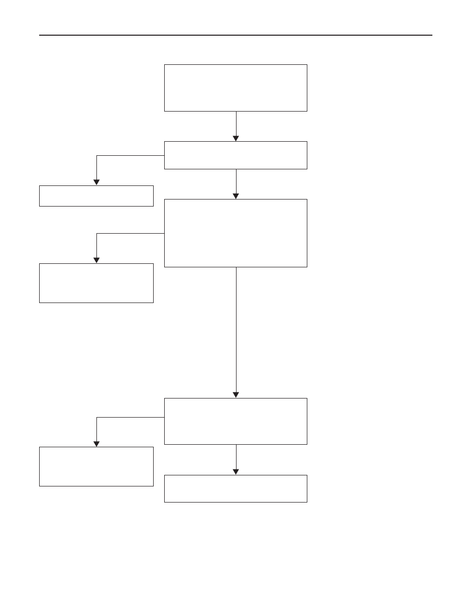
1. After releasing fixing screw of door scuff to the
passenger seat , remove the door scuff.
KAA5A020
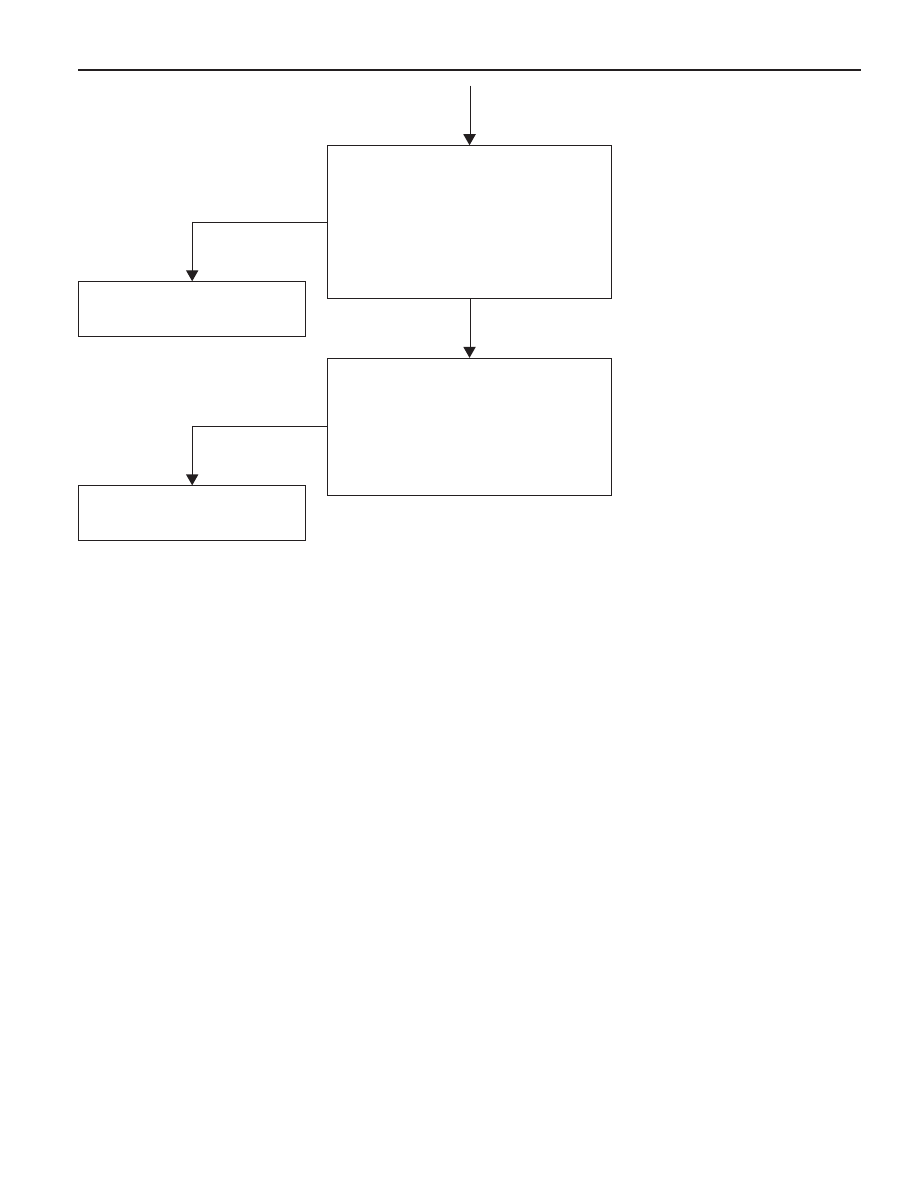
2. After releasing fixing bolt of cowl side trim, remove
cowl side trim.
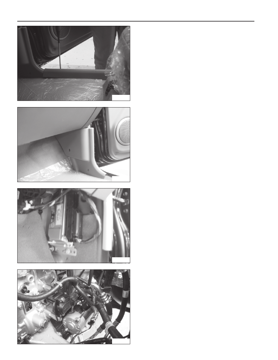
3. Remove pin of connector from the EGR module.
4. After releasing the fixing nut(3ea) of EGR module,
remove the the EGR module.
5. Installation should follow the removal procedure in
the reverse order.
THROTTLE POSITION SENSOR
Removal Procedure
1. Disconnect the TPS connector from the TPS.
2. After releasing the fixing bolt, remove the TPS.
Installation Procedure
1. Install temporary fixing bolt of TPS.
2. Install connector of TPS on the TPS.
3. Check the voltage of TPS by using SCAN-100.
4. Install completely fixing bolt of TPS.
Нет комментариевНе стесняйтесь поделиться с нами вашим ценным мнением.
Текст