SsangYong Musso. Manual — part 482
AUTOMATIC TRANSMISSION 5A-105
21. Holding the cylinder horizontal, install the sleeve and clutch
plate assembly into the cylinder, with the crest of one wave
of the washer In line with one of the holes in the outside of
the cylinder, until the sleeve contacts the C2 wave washer.
22. Check the C4 clutch pack clearance using special tool No.
0555-331900. Refer to figure 8.25.
Notice
With the C2 wave spring compressed, and the clutch Pack
supporting a 2 k9 weight, the dimension from the underside
of the C2 pressure plate to the selective steel is to be
between 1.4- 1.8 mm. If the clutch is to be gauged from
the top of the pressure plate, then the dimension is to be
the actual thickness of the pressure plate plus 1.4-1.8 mm.
23. Use selective plates to achieve the correct specification. If
new friction plates are being fitted, remove the clutch pack
and soak the friction plates in ATF for a minimum of 5
minutes prior to reassembly.
Notice
The clutch pack clearance must be taken before the
elements are soaked in Automatic Transmission Fluid
(ATF).
24. Reassemble the sleeve and clutch pack into the cylinder.
Observe the alignment of the wave washer to the hole in
the cylinder.
25. Install the C2 clutch plates in the cylinder in the following
sequence:
!
Friction disc
!
Steel plate
!
Friction disc
!
Steel plate
!
Steel plate - 0574-000001, 0574-000003,
0574-000004, 0574-000005, 0574-000020,
0574-000021, or friction disc -0574-000002
!
Steel plate (selective)
!
Friction disc
!
Steel plate (selective)
!
Friction disc

5A-106 AUTOMATIC TRANSMISSION
29. Align the tangs and fit the nylon thrust washer onto the
C4 hub. Refer to figure 8.27.
30. Align and fit the C4 hub to the C2 clutch and the OWC
assembly.
31. Check the rotation of the C2 hub. While holding the
C4 hub, the C2 hub should rotate in the clockwise
direction and lockup in the anti-clockwise direction when
viewed from the C2 hub. Refer to figure 8.27.
Figure 8.27 - C2 - Hub Rotation
32. Apply petroleum jelly to the No. 5 thrust bearing and fit
it to the C4 hub. Refer to figure 8.19.
33. Remove the C2 clutch plates from the clutch cylinder.
34. Fit the thrust plate over the cylinder inner hub. Refer
to figures 8.24 and 8.19.
35. Engage the C2/C4 clutch hub assembly in the C4 clutch
plates.
36. Install the C2 clutch plates.
37. Install the C3 hub and secure it with the circlip, ensuring
that the circlip is firmly seated in its groove.
Refer to figure 8.32.
Figure 8.26 - Typical C2 Clutch Pack Clearance
26. Check the clutch pack clearance using only the weight
from tool No.0555-331900. Refer to figure 8.26.
Notice
With the clutch pack supporting a 2 kg weight, the
dimension from the C3 clutch hub locating step to the
friction plate is to be between 0.80-1.05 mm.
27. Use selective plates to achieve the correct specification.
If new friction plates are being fitted, remove the clutch
pack and soak the friction plates in ATF for a minimum
of 5 minutes prior to reassembly.
Notice
The clutch pack clearance must be taken before the
elements are soaked in ATF.
28. Lubricate and fit the 3-4 OWC and end caps to the C2
hub.
AUTOMATIC TRANSMISSION 5A-107
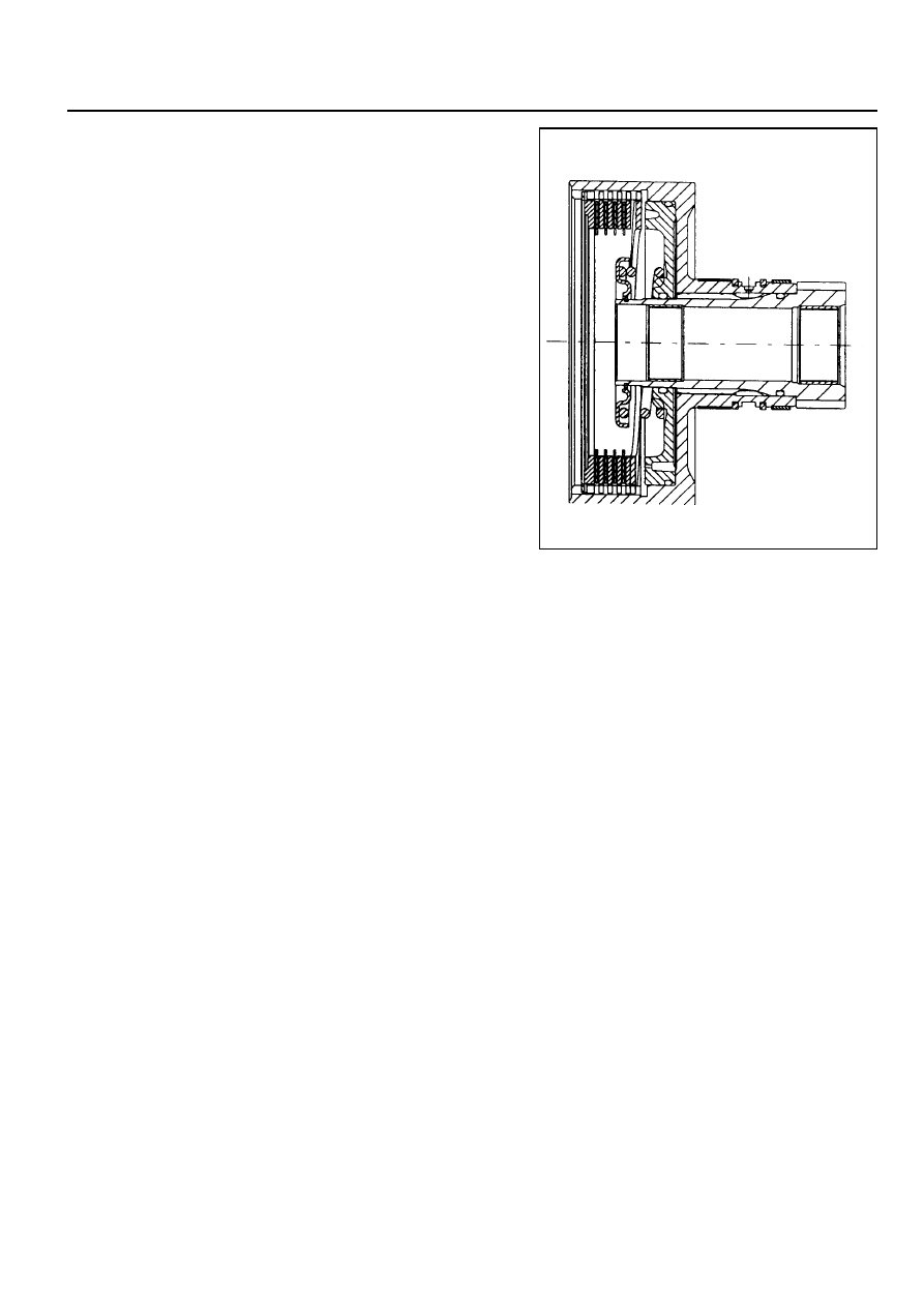
C3 Clutch and Reverse Sun Gear Assembly
To assemble the C3 clutch and reverse sun gear assembly
(refer to figure 8.28), proceed as follows.
1. Check the orifices in the cylinder are clear of obstructions.
2. Check the C3 cylinder bush outside diameter and the
centre support inside diameter are in good condition and
not damaged. Coat the sealing rings with automatic
transmission fluid and fit into the C3 cylinder grooves.
3. Check the reverse sun gear splines, grooves and thrust
face for condition. Coat the ‘O’ ring with automatic
transmission fluid and fit it to the groove of the reverse
sun gear.
4. Install the reverse sun gear in the C3 cylinder, ensuring
that the ‘O’ ring compression is adequate but not
excessive.
Notice
‘O’ rings must not be twisted in the grooves.
5. Coat the C3 piston ‘O’ rings with automatic transmission
fluid and fat the small ‘O’ ring onto the inner ring and the
large ‘O’ ring onto the outer ring of the C3 piston.
6. Check that the bleed orifices of the piston are clean and
clear of obstructions.
7. Install the C3 piston in the cylinder until the outside
diameter of the piston enters the inside diameter of the
cylinder.
Notice
Take care not to cut the ‘O’ ring.
8. Assemble the spring and spring retainer on the piston.
Using tool No. 0555-331899 compress the spring
sufficiently to enable the installation of the retaining circlip,
ensuring that the circlip is firmly seated in the groove, and
remove the tool.
9. Fit the C3 wave plate to the C3 piston face, ensuring that
one crest of the wave plate of the C3 piston face is aligned
over one of the piston orifices.
10. Assemble the clutch plates and discs into the cylinder in
the following sequence :
!
Steel plate
!
Friction disc
!
Steel plate
!
Steel plate - 0574-000001, 0574-000003,
0574-000004,0574-000005,0574-000020,
0574-000021, or friction disc -0574-000002
!
Steel plate (selective)
!
Friction disc
!
Steel plate (selective)
!
Friction disc
11. Align and fit the pressure plate with the counterbore facing
away from the clutch plates.
Figure 8.28 - C3 Clutch and Reverse Sun Gear

5A-108 AUTOMATIC TRANSMISSION
12. Install the circlip.
13. Check the C3 clutch clearance (refer to figure 8.29) using
special tool No.0555-331900 in the following manner
(weight only).
a. Place the weight on the pressure plate and measure
the distance from the end of the cylinder to the top of
the pressure plate.
b. Record this figure.
c. Remove the weight.
d. Lift the pressure plate up against the circlip and
measure the distance from the end of
the cylinder to the top of the pressure plate.
e. Record this figure.
f.
Subtract the second reading from the first reading to
obtain the clutch pack clearance.
Notice
With the clutch pack supporting a weight of 2 kg, the
clearance between the snap ring and the top of the
pressure plate is to be between 1.20-1.45 mm.
14. If new friction plates are being fitted, remove the clutch
pack and soak the friction elements in automatic
transmission fluid for a minimum of five minutes prior to
reassembly.
Notice
The clutch pack clearance must be taken before the
elements are soaked in automatic transmission fluid.
Figure 8.29 - Typical C3 Clutch Assembly
Clearance
Нет комментариевНе стесняйтесь поделиться с нами вашим ценным мнением.
Текст