SsangYong Musso. Manual — part 481
AUTOMATIC TRANSMISSION 5A-101
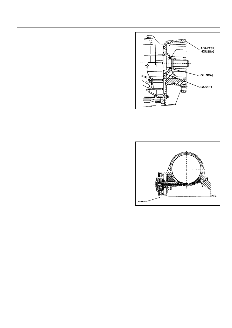
Extension Housing Assembly
To assemble the extension housing assembly, proceed as
follows.
1. Check the condition of the extension housing roller bearing.
Replace if necessary (RWD models). Install the new bearing
from rear of extension housing. Press on the branded face
of bearing only.
2. Install a new seal to the extension housing or adaptor
housing. Refer to figure 8.21.
Notice
Do not use petroleum jelly to hold the gasket in position.
3. Position a new gasket onto the extension housing or adaptor
housing.
Notice
See section 8.3.17 for the procedure to assemble the output
flange assembly - RWD models.
4. Install the extension housing (RWD) or adaptor housing
(4WD) and torque the bolts to specification.
Front Servo Assembly
NOTICE
Ensure that the front servo snap ring is installed correctly.
Orient the circlip with the gap at the bottom, near the pan rail.
Refer to figure 8.22.
To assemble the front servo assembly (refer to figure 8.22),
proceed as follows.
1. Lubricate the cover ‘O’ ring with automatic transmission fluid
and fit to the cover.
2. Lubricate the piston ‘O’ rings with automatic transmission
fluid and fit to the piston.
3. Assemble the piston, push rod, spring, belleville washer,
seat and retaining ring.
4. Fit the piston push rod assembly into the front servo cover.
5. Install the front servo block and spring into the case.
6. Install the front servo assembly into the case.
7. Compress the servo cover and fit the servo cover retaining
circlip, aligning the gap with the pan rail, and ensuring that
it is completely seated in its groove.
Figure 8.21 - Extension Housing
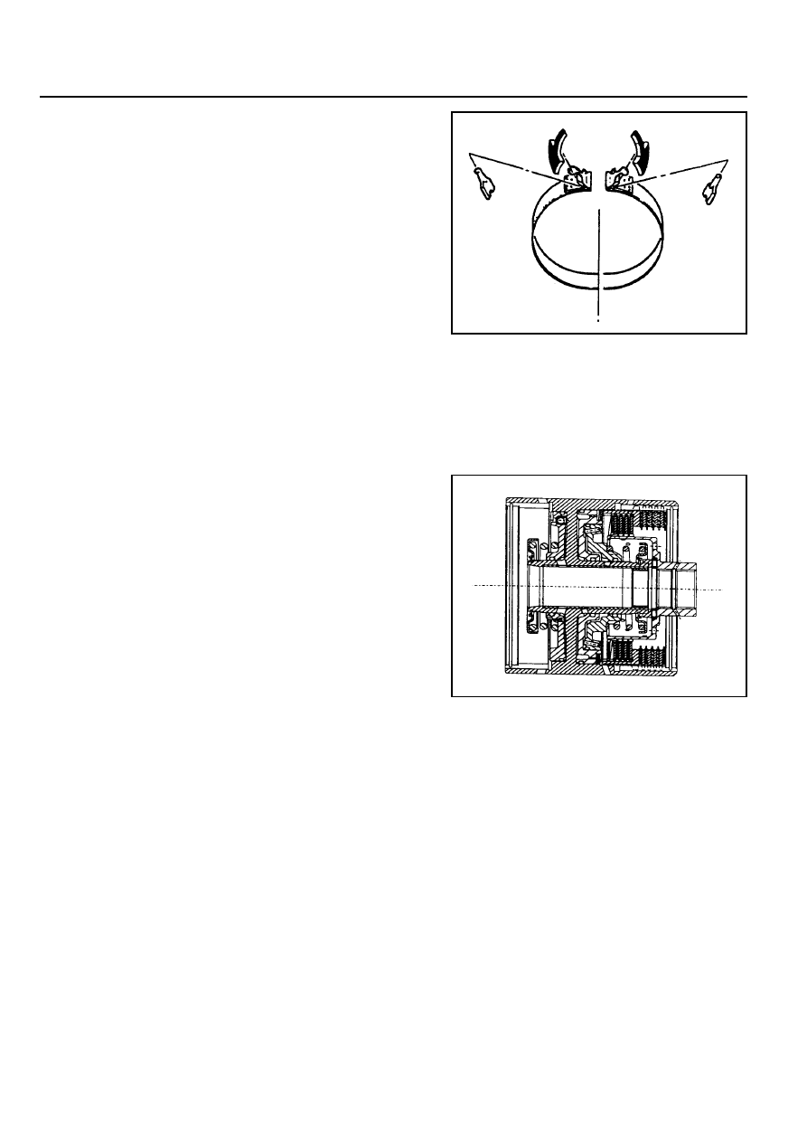
Figure 8.22 - Front Servo and Band
5A-102 AUTOMATIC TRANSMISSION
Front Band Assembly
To assemble the front band assembly, proceed as follows.
1. Install the reaction anchor strut to the case.
2. Check the band for ally cracks or damage along its lining
and metal backing.
3. Position the strut retainers on the band (refer to figure
8.23).
NOTICE
If fitting a new band, soak the band in automatic
transmission fluid for a minimum of 5 minutes prior to
assembly.
4. Install the front band into the transmission case, ensuring
that it is properly seated in place.
5. Position the reaction strut in its retaining clip and engage
it with the band and anchor strut.
Position the apply strut in its retaining clip and engage it
with the band and the servo piston rod.
C2/C4 Clutch Assembly
Notice
1. Check pistons for cracks.
2. Do not mix the clutch piston return springs.
3. Ensure that the snap rings are fitted correctly.
To assemble the C2/C4 clutch assembly (refer to figure 8.24),
proceed as follows.
1. Check the feed orifices in the cylinder bore are clear of
obstructions.
2. Check the C2 piston bleed orifices are clear of obstructions.
3. Lubricate the ‘O’ rings with automatic transmission fluid.
Notice
‘O’ rings must not be twisted in the grooves.
4. Fit the small ‘O’ ring onto the inner groove, and the large
‘O’ ring onto the outer groove of the piston.
5. Check the C4 piston bleed orifices are clear of obstructions.
6. Lubricate the ‘O’ rings with automatic transmission fluid.
7. Fit the small ‘O’ rings onto the inner groove and the large
‘O’ rings onto the outer groove of the piston.
8. Position the clutch cylinder with the C2/C4 cavity facing
upwards.
9. Fit the C4 piston into the C2 piston with the bleed orifices
in alignment.
10. Install the C2/C4 piston assembly into the cylinder, with the
piston bleed orifices aligned with the holes on the outside
of the cylinder, until the outer diameter of the C2 piston
enters the inner diameter of the cylinder.
Figure 8.23 - Front Band Strut Installation
Figure 8.24 - Typical C2/C4 Clutch Assembly
AUTOMATIC TRANSMISSION 5A-103
11. Assemble the piston return spring to the piston, and fit the
spring retainer over the spring.
Notice
The wire diameter of this spring is 4.3 mm.
12. Using special tool No. 0555-331899, compress the spring
sufficiently to enable the installation of the retaining circlip
ensuring that the circlip is firmly seated in its groove, then
remove the tool.
13. Check the C1 piston check valves are not damaged and
are free to move, and that the cylinder feed orifices are
clear of obstructions.
14. Lubricate the’0’rings with automatic transmission fluid and
fit them to their respective grooves.
Notice
‘O’ rings must not be twisted in the grooves.
15. Position the cylinder with the C1 cavity upwards. Install the
piston into the cylinder until the outer diameter of the piston
enters the inner diameter of the cylinder.
16. Install the spring and spring retainer onto the piston.
Notice
The wire diameter of this spring is 5.26 mm.
17. Using special tool No. 0555-331899, compress the spring
sufficiently to enable the installation of the retaining circlip
ensuring that the circlip is firmly seated in its groove, then
remove the tool.
18. Install the C2 wave washer into the cylinder with the crest
of one wave covering one of the bleed orifices in the C2
piston.
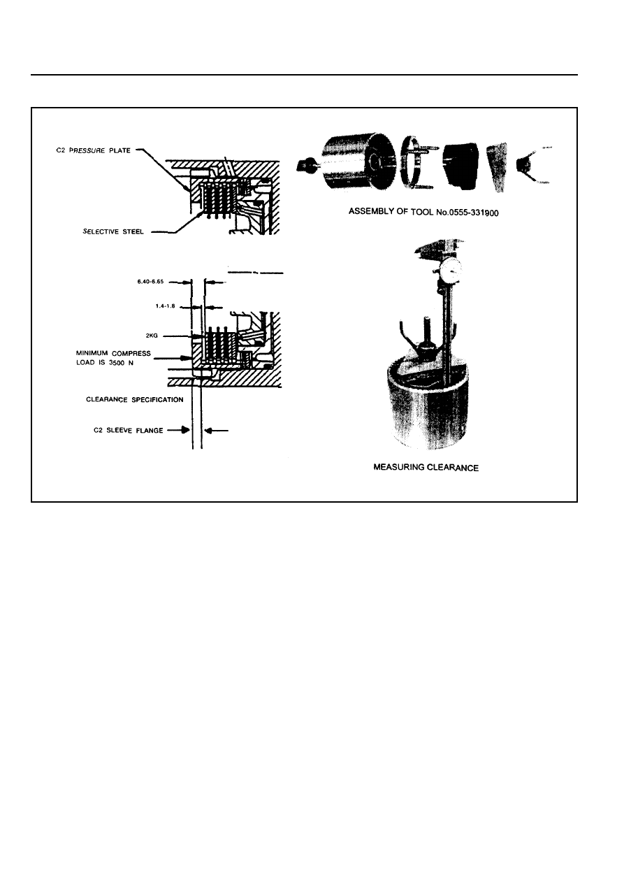
19. Measure and record the thickness of the flange of the C2
sleeve. Refer to figure 8.25.
20. Install the C4 clutch plates and wave washer into the C2
actuating sleeve, with the rounded edge of the steel plates
down, in the following sequence:
!
Steel plate (selective)
!
Friction disc
!
Steel plate
!
Friction disc
!
Steel plate
!
Friction disc
!
Steel plate
!
Wave washer
5A-104 AUTOMATIC TRANSMISSION
Figure 8.25 - C4 Clutch Pack Clearance
Нет комментариевНе стесняйтесь поделиться с нами вашим ценным мнением.
Текст