SsangYong Musso. Manual — part 424
1F3-46 OM600 ENGINE CONTROLS
Tools Required
000 589 77 03 00 Box Wrench Insert
601 589 00 08 00 Flange
601 589 05 21 00 Locking Screw
601 589 05 14 00 Assembly CageRemoval
FUEL INJECTION PUMP
Preceding Work : Removal of vacuum pump
Removal of air cleaner housing
Removal of intake manifold
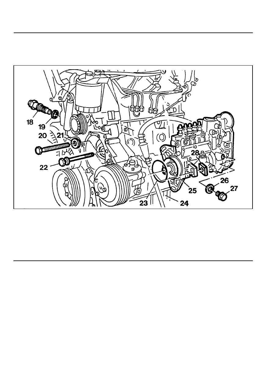
18 Chain Tensioner. . . . . . . . . . . 80Nm
19 Seal . . . . . . . . . . . . . ... Replace
20 Bolt(Left-Hand Thread) . . . . . . . .. 46Nm
21 Washer
22 Bolt . . . . . . . . . . . . . . . 23Nm
23 Seal . . . . . . . . . . . . . ... Replace
24 Oil Pan
25 Fuel Injection Pump
26 Seal . . . . . . . . . . . . . ... Replace
27 Screw Plug . . . . . . . . . . . . . 30Nm
28 Square Nut
OM600 ENGINE CONTROLS 1F3-47
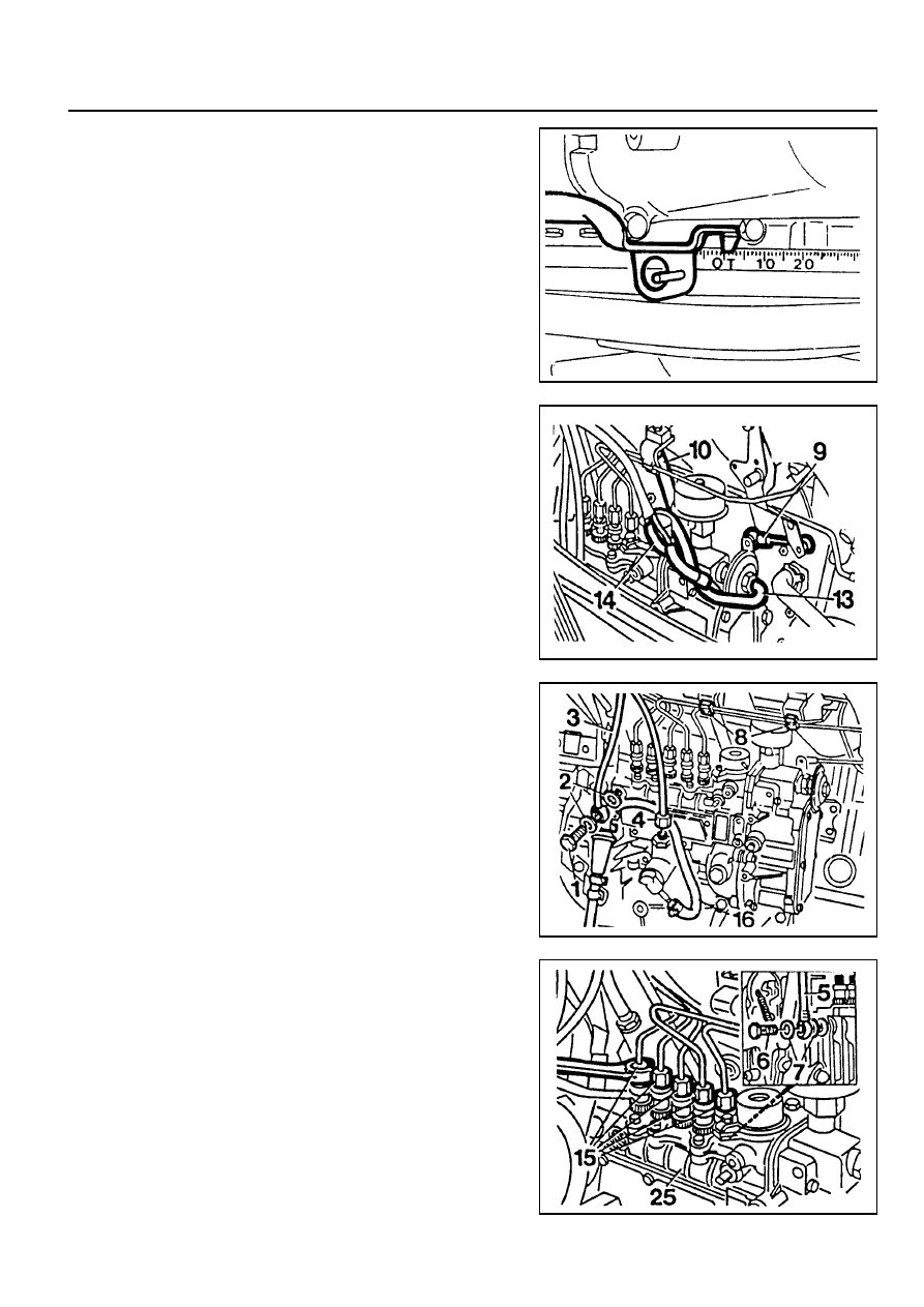
2. Remove the connecting rod (9).
3. Disconnect the vacuum lines (13, 14).
4. Remove the accelerator control damper (10).
(Manual transmission vehicle)
5. Remove the suction line (16) and pressure line (4).
6. Remove the banjo bolt (1) and then remove the seal (2)
and fuel line (3).
7. Remove the plastic clip (8) on the injection line.
Removal Procedure
1. Position then no.1 cylinder at 15° ATDC.
Notice
Do not rotate the engine in opposition direction of engine
rotation.
8. Disconnect the injection lines (15) from the injection pump
(25).
9. Remove the banjo bolt (1) and then remove the seal (7)
and return line (5).
1F3-48 OM600 ENGINE CONTROLS
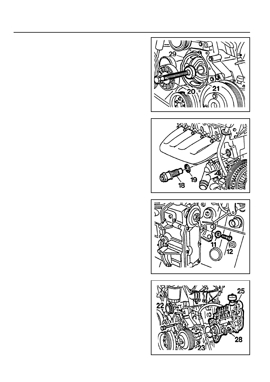
10. Install the assembly cage (29) and remove the bolt (20)
and pull off the washer (21).
Notice
Be careful that the bolt (20) is left hand thread.
Assembly Cage 601 589 05 14 00
11. Remove the chain tensioner (18) and seal (19).
12. Remove the bolt (12) and pull off the washer (11).
13. Remove the bolt (22) and pull off the square nut (28).
14. Pull out the fuel injection pump (25) and seal (23).
OM600 ENGINE CONTROLS 1F3-49
Installation Procedure
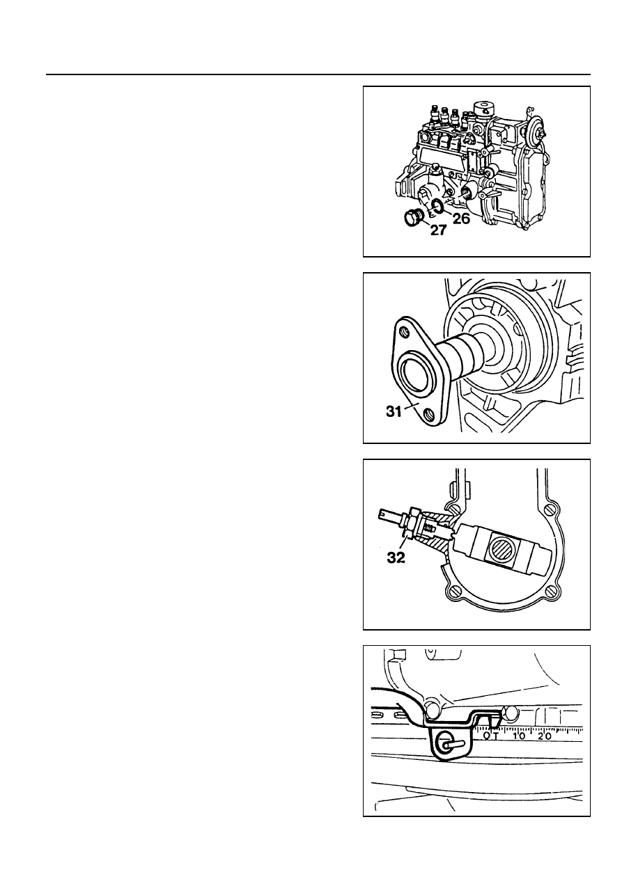
1. Remove the screw plug (27) and seal (26) and collect oil in
a vessel.
2. Insert flange (31) onto the injection pump camshaft and
turn until the cam of the governor is visible in the hole.
Flange 601 589 00 08 00
3. Tighten the locking screw.
Locking Screw 601 589 05 21 00
4. Ensure that the No.1 cylinder is positioned at ATDC 15°.
Нет комментариевНе стесняйтесь поделиться с нами вашим ценным мнением.
Текст