SsangYong Musso. Manual — part 425
1F3-50 OM600 ENGINE CONTROLS
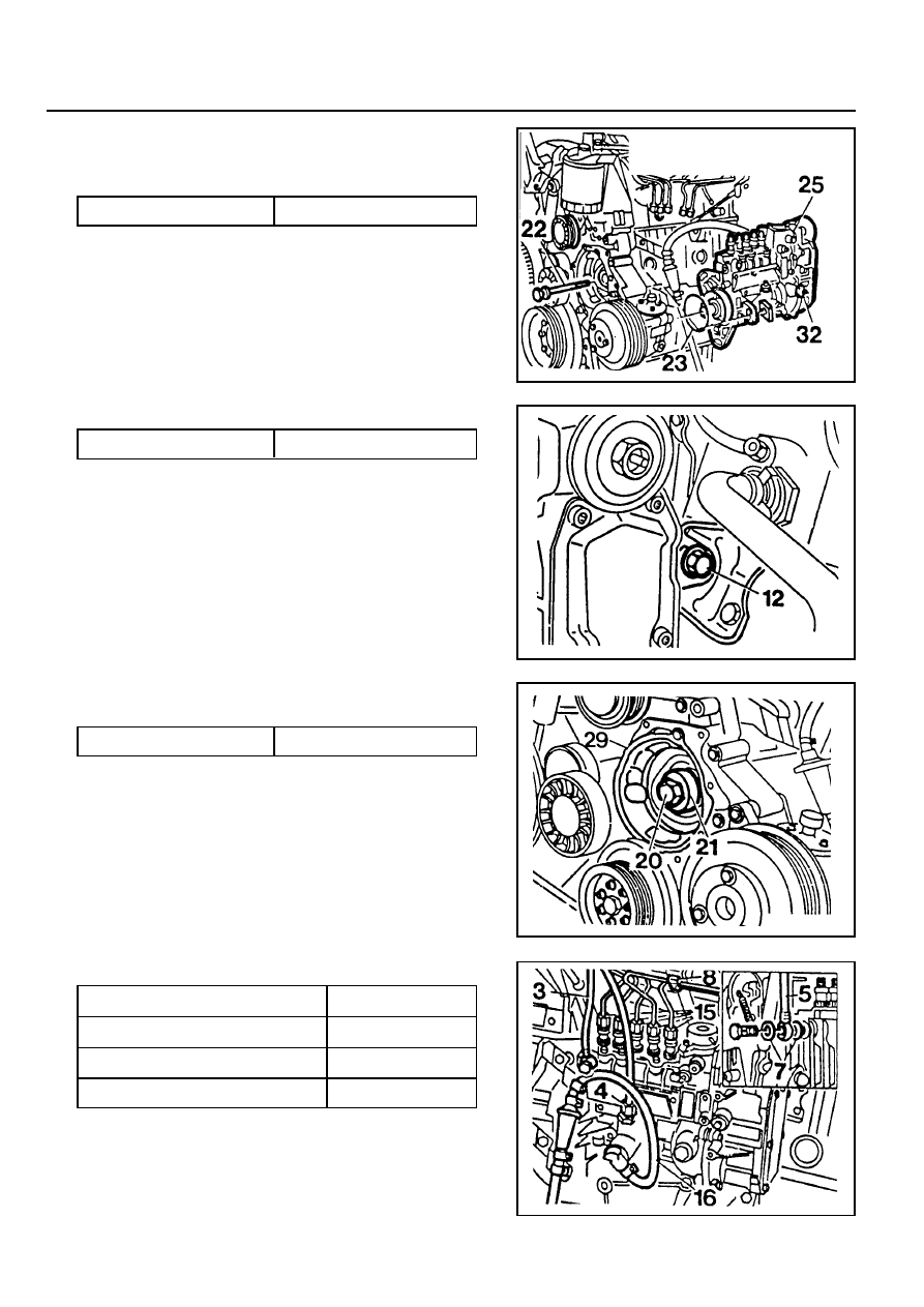
10. Connect the fuel pipes
Notice
Replace the seal.
Box Wrench Insert 000 589 77 03 00
Return Line
Fuel Injection Line
Fuel feed Line
Suction and Pressure Line
46 Nm
18 Nm
13 Nm
13 Nm
5. Coat the new seal (23) with engine oil and install it.
6. Insert the fuel injection pump (25) and tighten the bolts
(22).
7. Remove the locking screw (32).
Tightening Torque
23 Nm
8. Tighten the bolt(12).
9. Insert the washer (21) and tighten the bolts (20) and then
remove the assembly cage (29).
Tightening Torque
23 Nm
Tightening Torque
46 Nm
OM600 ENGINE CONTROLS 1F3-51
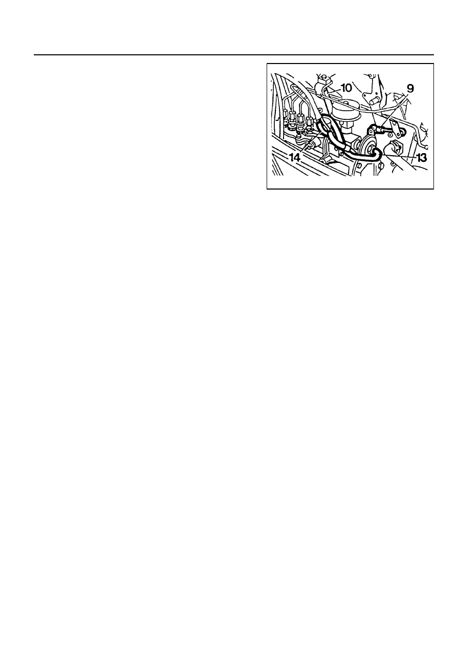
12. Connect the vacuum line (13, 14).
13. Connect the connecting rod (9).
14. Connect the accelerator control damper (10).
(Manual transmission vehicle)
15. Install the chain tensioner.
16. Install the vacuum pump.
17. Check the start of delivery.
18. Adjust the idle speed.
11. Assemble the plastic clip (8).

SECTION 1G3
OM600 ENGINE INTAKE & EXHAUST
Specifications . . . . . . . . . . . . . . . . . . . . . . . 1G3-1
Fastener Tightening Specifications . . . . . . . . 1G3-1
Schematic and Routing Diagrams . . . . . . . 1G3-2
EGR Circuit . . . . . . . . . . . . . . . . . . . . . . . . . . 1G3-2
Maintenance and Repair . . . . . . . . . . . . . . 1G3-3
On-Vehicle Service . . . . . . . . . . . . . . . . . . . . 1G3-3
TABLE OF CONTENTS
Caution: Disconnect the negative battery cable before removing or installing any electrical unit or when a
tool or equipment could easily come in contact with exposed electrical terminals. Disconnecting this cable
will help prevent personal injury and damage to the vehicle. The ignition must also be in LOCK unless otherwise
noted.
SPECIFICATIONS
FASTENER TIGHTENING SPECIFICATIONS
Application
Air Cleaner Housing Cover Nut
Intake Manifold Bolt (M8 x 20)
Intake Manifold Bolt (M8)
Exhaust Mainfold Stud Bolt
Exhaust Pipe Nut (Engine)
Exhaust Pipe Bolt
N
•••••
m
9 - 11
22.5 - 27.5
22.5 - 27.5
9.5 - 12.5
15 - 28
28 - 47
Air Cleaner and Inlet Duct & Hose . . . . . . . . 1G3-3
Intake and Exhaust Manifold . . . . . . . . . . . . . 1G3-5
Turbocharger . . . . . . . . . . . . . . . . . . . . . . . 1G3-8
Charge Air System Diagram . . . . . . . . . . . . . 1G3-8
Intercooler . . . . . . . . . . . . . . . . . . . . . . . . . . 1G3-9
Turbocharger Assembly . . . . . . . . . . . . . . . 1G3-11
1G3-2 OM600 ENGINE INTAKE & EXHAUST
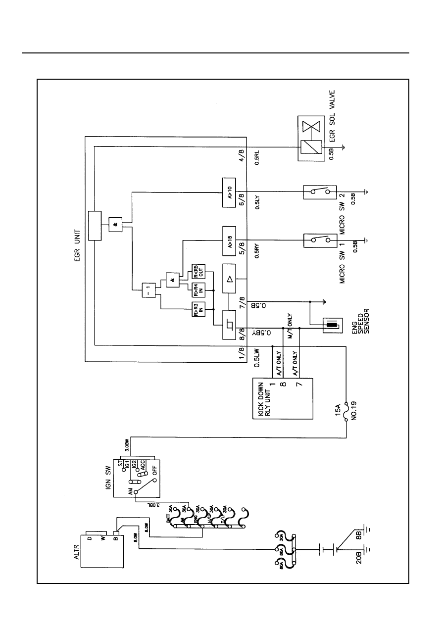
SCHEMATIC AND ROUTING DIAGRAMS
EGR CIRCUIT
Нет комментариевНе стесняйтесь поделиться с нами вашим ценным мнением.
Текст