SsangYong Musso. Manual — part 201

1F-388 ENGINE CONTROLS
SSANGYONG Y158
Step
Action
Value(s)
Yes
No
DTC P0463 Fuel Level Sensor Short Circuit to Battery (Cont'd)
11
12
1. Using the scan tool, clear the DTCs.
2. Start the engine and idle at normal operating
temperature.
3. Operate the vehicle within the conditions for setting
this DTC as specified in the supporting text.
Does the scan tool indicate that this diagnostic ran and
passed?
Check if any additional DTCs are set.
Are any DTCs displayed that have not been diagnosed?
-
Go to Step 12
Go to Step 2
-
Go to
applicable
DTC table
System OK
ENGINE CONTROLS 1F-389
SSANGYONG Y158
BLANK
1F-390 ENGINE CONTROLS
SSANGYONG Y158
DIAGNOSTIC TROUBLE CODE (DTC) P0501
VEHICLE SPEED SENSOR NO SIGNAL
Circuit Description
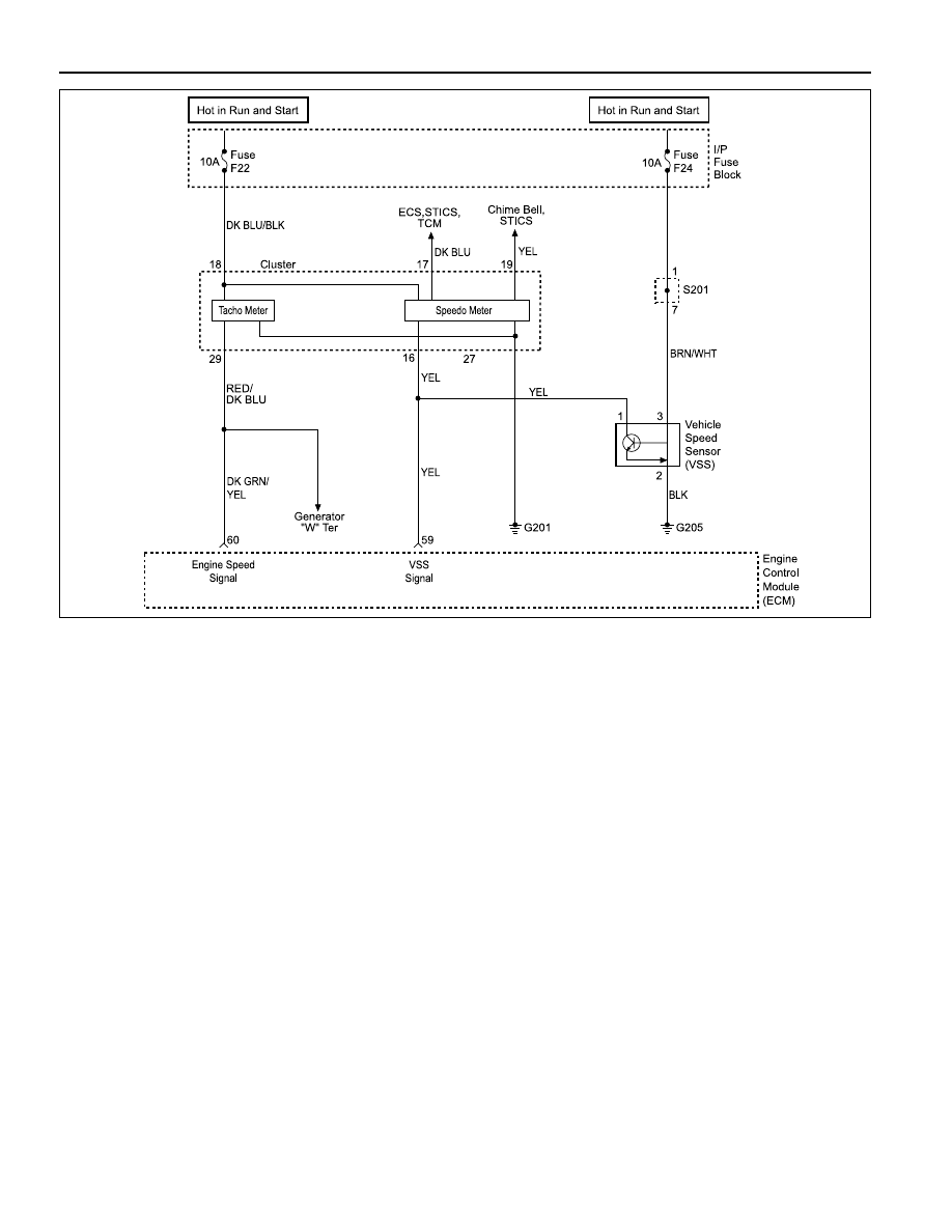
Vehicle speed information is provided to the Engine
Control Module (ECM) by the Vehicle Speed Sensor
(VSS). The VSS is a permanent magnet generator and
produces a pulsing voltage vehicle. The Alternating
Current (AC) voltage level and the number of pulses in-
creases with vehicle speed. The ECM converts the
pulsing voltage into mph (km/h) and then supplies the
necessary signal to the instrument panel for speedome-
ter/ odometer operation and to the cruise control module
and multi-function alarm module operation. This Diag-
nostic Trouble Code (DTC) will detect. if vehicle speed
is reasonable according to engine rpm and load.
Conditions for Setting The DTC
•••••
Vehicle speed signal threshold is more than 265km/h
(165 mph) or less than 2.4km/h (1.5 mph).
•••••
Engine speed threshold is between 2790 rpm and 3600
rpm for A/T and 3000 rpm and 3900 rpm for M/T.
•••••
P/N switch is off.
•••••
Time threshold is more than 3.0 seconds for A/T and
more than 5.0 seconds for M/T.
•••••
Engine speed limitation is not active.
Action Taken When the DTC Sets
•••••
The Malfunction Indicator Lamp (MIL) will illuminate
after two consecutive driving cycles in which the diag-
nostic runs with the fault active.
•••••
The ECM will record operating conditions at the time
the diagnostic fails. This information will be stored in
the Freeze Frame and Failure Records buffers.
•••••
A history DTC is stored.
Conditions for Clearing the MIL/DTC
•••••
The MIL will turn off after three consecutive driving
cycles in which the diagnostic runs without a fault.
•••••
A history DTC will clear after 40 consecutive warm-
up cycles without a fault.
•••••
The DTC(s) can be cleared by using the scan tool.
Diagnostic Aids
An intermittent problem may be caused by a poor con-
nection, rubbed-through wire insulation, or a wire that is
broken inside the insulation.
VSS signal circuit should be thoroughly checked for the
following conditions :
•••••
Backed-out terminals
YAA1F88A

ENGINE CONTROLS 1F-391
SSANGYONG Y158
1
Step
Action
Value(s)
Yes
No
DTC P0501 Vehicle Speed Sensor No Signal
-
Go to Step 2
Go to “Euro
On-Board
Diagnostic
System Check”
2
3
4
7.40 v
Go to Step 5
Go to Step 7
5
Perform the Euro On-Board Diagnostic (EOBD) System
Check.
Is the system check complete?
Notice: Running the vehicle in gear with the wheels
hanging down at full travel will damage the drive axles.
1. Turn the ignition ON, with the engine OFF.
2. Install a scan tool.
3. Raise the drive wheels.
4. Support the lower control arms so that drive axles
are in a horizontal (straight) position.
5. Allow the engine to idle in gear.
Does the scan tool display vehicle speed above the
specified value?
1. Turn the ignition ON, with the engine OFF.
2. Review the Freeze Frame data and note the
parameters.
3. Operate the vehicle within the Freeze Frame
conditions and Conditions for Setting this DTC.
Does the scan tool display the vehicle speed above the
specified value?
1. Turn the ignition OFF.
2. Disconnect the Vehicle Speed Sensor (VSS)
connector.
3. Turn the ignition ON, with the engine OFF.
4. Using a Digital Voltmeter (DVM) connected to
ground, measure the voltage in the Vehicle Speed
Sensor (VSS) signal circuit, at terminal 1.
Is the voltage near the specified value?
Using a DVM, measure the voltage at terminal 3 of the
VSS harness connector.
Is the voltage near the specified value?
Probe the VSS ground circuit, terminal 2 at the VSS
harness connector with a test light connected to B+.
Does the test light illuminate?
0 km/h
Go to Step 12
Go to Step 4
0 km/h
Go to Step 3
Go to Step 4
11 - 14 v
Go to Step 6
Go to Step 8
6
-
Go to Step 10
Go to Step 9
•••••
Improper mating
•••••
Broken locks
•••••
Improperly formed
•••••
Damaged terminals
•••••
Poor terminal-to-wire connection
•••••
Physical damage to the wiring harness
Test Description
Number(s) below refer to the step number(s) on the
Diagnostic Table.
1. Euro On-Board Diagnostic (EOBD) System Check
prompts the technician to complete some basic
checks and store the freeze frame and failure re-
cords data on the scan tool if applicable. This
creates an electronic copy of the data taken when
the malfunction occurred. The information is then
stored on the scan tool for later reference.
3. Proper engine loads cannot be achieved in a shop
environment to properly run the vehicle within the
Freeze Frame Data conditions. It will be necessary
to drive the vehicle on the road to obtain the proper
engine loads.
4. This step verifies that the ECM is supplying a signal
voltage to the vehicle speed sensor.
11. The replacement ECM must be reprogrammed. Re-
fer to the latest Techline procedure for ECM repro-
gramming.
Нет комментариевНе стесняйтесь поделиться с нами вашим ценным мнением.
Текст