SsangYong Musso. Manual — part 316
1F1-22 M162 ENGINE CONTROLS
Failure
code
Item
Checking method
Test
step
Requirement
Specified
value
Possible cause
⇒
6.1
•••••
Crankshaft
position
sensor:
- Resistance
•
Ignition:OFF
- Disconnect the
coupling "NO.2"
from ECU
•
Cable
•
Crankshaft position
sensor
⇒
6.0
•
Engine:in cranking
99
100
Measure the
signal (refer to
figure 6)
•••••
Crankshaft
position
sensor:
- Signal
17,
18,
20,
67,
•
⇒
6.1
•
Increament failure in
driven plate
> 5 V -
99
100
99
100
1050 - 1400
Ω
⇒
7.0
•
Engine:in cranking
104
106
•
⇒
7.1
•
Cable
•
Camshaft position
sensor
Measure the
signal(refer to
figure 7)
•••••
Camshaft
position
sensor:
- Signal
⇒
4.0
•
Ignition:ON
69
72
11 -14 V
•••••
Ignition
coil(T1/2)
- No.3,4
Cylinder
65,
•
Cable
•
Ignition coil(T1/2)
•
Fuse No.17
•
Engine:in cranking
> 10 V
•
Engine:in idling
- Voltage
(alternating)
•
Engine:in cranking
•
Engine: in idling
> 2.5 V -
19,
58,
⇒
5.0
•
Ignition:ON
69
70
11 -14 V
•••••
Ignition
coil(T1/3)
- No.1,6
Cylinder
66,
•
Cable
•
Ignition coil(T1/3)
•
Fuse No.17
•
Engine:in cranking
> 10 V
17,
18,
20,
67,
Voltage value
is increased
when engine
rpm is
increased
M162 ENGINE CONTROLS 1F1-23
Failure
code
Item
Checking method
Test
step
Requirement
Specified
value
Possible cause
106
11
The value will
be changed in
1.2 - 1.7 V
- Voltage
(alternating)
0.9 - 1.6
Ω
71
11
71
72
•
Engine:in cranking
⇒
7.1
•
Ignition:ON
- Remove the
connector from the
Camshaft position
sensor between
No.1 terminal and
No.3 terminal.
1
3
11 -14 V
•••••
Camshaft
position
sensor
(E23 only)
- Power
supply
•
Cable
•
OVPR
•••••
Ignition
coil(T1/1)
- primary coil
voltage
(No.2 and 5
cylinder)
•
Engine:in cranking
(starter operating)
- Measuring range:
400 V
- Time range: 100 %
(using engine tester)
•
Ignition:OFF
200 - 350 V
Camshaft position
sensor
64,
⇒
8.0
•
⇒
8.1
⇒
8.1
•••••
Connecting
resistance of
ignition coil
between T1/
1 and T1/2
•
Cable
•
Ignition coil T1/1
•
Ignition coil T1/2
72
11
•••••
Ignition
coil(T1/2)
- primary coil
voltage
(No.3 and 4
cylinder)
•
Engine:in cranking
(starter operating)
- Measuring range:
400 V
- Time range: 100 %
(using engine tester)
200 - 350 V
65,
⇒
9.0
•
⇒
9.1
0.9 - 1.6
Ω
72
71
•
Ignition:OFF
⇒
9.1
•••••
Connecting
resistance of
ignition coil
between T1/
2 and T1/1
•
Cable
•
Ignition coil T1/1
•
Ignition coil T1/2
The
resistance of
ignition coil at
20
°
C is
approached
0.6
Ω
The
resistance of
ignition coil at
20
°
C is
approached
0.6
Ω
1F1-24 M162 ENGINE CONTROLS
Failure
code
Item
Checking method
Test
step
Requirement
Specified
value
Possible cause
8 - 20 KV
•••••
Ignition coil
(T1/1, T1/2,
T1/3)
- Secondary
ignition
voltage
> 10 M
Ω
117
118
•
Engine:in cranking
- Select the ignition
coil in order of T1/1,
T1/2
- Measuring range:
20KV
- Time range:100 %
•
Ignition:OFF
- Disconnect the
coupling "No.2" from
ECU.
⇒
12.0
•••••
Knock
sensor 1
- Resistance
(cylinder
No1, 2, 3)
•
Connecting
condition
•
Cable
•
ECU
⇒
11.0
64,
65,
66,
Engine tester
•
⇒
11.1
•
Ignition plug
•
ECU
•
High tension cable
6 - 8.5 K
Ω
•••••
Ignition coil
(T1/1, T1/2,
T1/3)
- Secondary
coil
resistance
•
Remove the high
tension cable of T1/
1, T1/2, T1/3.
⇒
11.1
Ignition coil
(T1/1, T1/2, T1/3)
•
Ignition coil T1/1
•
Ignition coil T1/2
•
Ignition coil T1/3
TM.4a
TM.4b
56,
11
•••••
Ignition
coil(T1/3)
- primary coil
voltage
(No.1 and 6
cylinder)
•
Engine:in cranking
(starter operating)
- Measuring range:
400 V
- Time range: 100 %
200 - 350 V
66,
⇒
10.0
•
⇒
10.1
0.9 - 1.6
Ω
70
72
•
Ignition:OFF
⇒
10.1
•••••
Connecting
resistance of
ignition coil
between T1/
3 and T1/2
•
Cable
•
Ignition coil T1/3
•
Ignition coil T1/2
> 10 M
Ω
114
115
•
Ignition:OFF
- Disconnect the
coupling "No.2" from
ECU.
⇒
13.0
•••••
Knock
sensor 2
- Resistance
(cylinder
No.4, 5, 6)
•
Connecting
condition
•
Cable
•
ECU
57,
The
resistance of
ignition coil at
20
°
C is
approached
0.6
Ω
M162 ENGINE CONTROLS 1F1-25
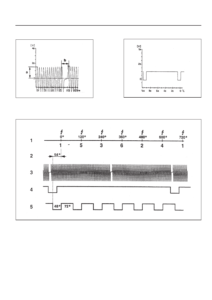
Reference Figures
Figure 6. Crankshaft Position Sensor Signal
a
Voltage
b
Identifying the No.1 - 2 Missing Teeth
Figure 7. Camshaft Position Sensor Signal
Figure 8. Signal Function
1
Crank Angle
2
Cylinder
3
Crankshaft Position Sensor Signal
4
Camshaft Position Sensor Signal
5
RPM Signal
Нет комментариевНе стесняйтесь поделиться с нами вашим ценным мнением.
Текст