SsangYong Musso. Manual — part 315
1F1-18 M162 ENGINE CONTROLS
Failure
code
Item
⇒
18.1
Checking method
Test
step
Requirement
Specified
value
Possible cause
73
2
8 - 12
Ω
•••••
Camshaft
actuator:
Solenoid
resistance
⇒
21.0
•••••
Purge
control
valve:
- Vacuum
control
•
Engine:in idling/
normal operating
temperature
•
Vacuum line
•
Purge control valve
•
Cable
•
Camshaft actuator
Diagnosis
socket
⇒
19.0
73
69
Engine is
unstable or
stopped
•••••
Camshaft
actuator:
Mechanical
Actuation
•
Mechanical failure of
camshaft actuator
⇒
20.0
•
Engine:in idling
34
11
The purge
control valve
should be
operated after
approx.
1minute.
(refer to figure
5)
•••••
Purge
control
valve:
- Operating
226,
227,
•
ECU
•
Cable
•
Purge control valve
•
Ignition:ON
0.3 - 0.5 A
- Current
consumption
10
34
Creating
above 50mbar
of vacuum
after approx.
1 minute
⇒
22.0
•
Ignition:OFF
38
37
•
Data bus
•
⇒
22.1
•
⇒
22.2
55 - 65
Ω
•••••
CAN data
bus
•
Ignition:OFF
•
Engine:in idling
- connect the bridge
to the test box for
approx. 10 seconds
40,
41,
54,
Connect the vacuum
gauge between the
control valve and
canister
22,23,
24,26,
27,29,
30,31,
59,60,
M162 ENGINE CONTROLS 1F1-19
Failure
code
Item
⇒
22.1
Checking method
Test
step
Requirement
Specified
value
Possible cause
38
37
115 - 125
Ω
•••••
CAN module
resistance in
ABS, ABD,
ASR control
unit
•
Cable
•
ABS, ABD, ASR
control unit
•
Ignition:OFF
- disconnect the
coupling "No.1" from
ECU.
⇒
22.2
38
37
115 - 125
Ω
•••••
CAN module
resistance in
ECU control
unit
•
ECU
•
Ignition:OFF
- disconnect the
coupling "No.1" from
ECU.
⇒
23.0
5
58
11 - 14 V
•••••
Diagnosis
cable
operating
•
ECU
•
Cable
•
Ignition:ON
22,23,
24,26,
27,29,
30,31,
59,60,
1F1-20 M162 ENGINE CONTROLS
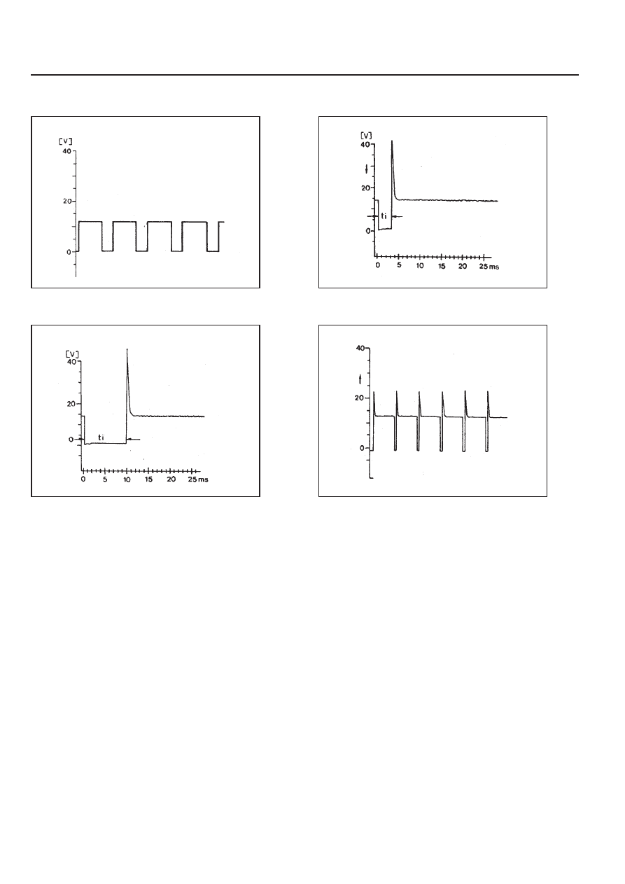
Reference Figures
Figure2. RPM Sgnal Output
Figure 3. Injection Valve Wave(at idle speed)
Figure 4. Injection Valve Wave(at sharp
acceleration)
Figure 5. Purge Control Valve Operationg Wave
M162 ENGINE CONTROLS 1F1-21
Failure
code
Item
Checking method
Test
step
Requirement
Specified
value
Possible cause
10
12
11 - 14V
•••••
ECU:power
supply
- terminal
30(TM.30)
⇒
2.2
•••••
Power
supply:
- terminal
87(TM.87)
•
Ignition:ON
•
Power supply cable
•
OVPR
IGNITION SYSTEM TEST
08,
•
⇒
1.1
•
⇒
1.2
⇒
1.1
•
Ignition:ON
10
2
11 - 14V
•••••
Ground
cable:
- Battery
ground
•
Ground cable
•
Ground condition
(figure 1)
Diagnosis
socket
69
2
Diagnosis
socket
⇒
1.2
•
Ignition:ON
1
12
11 - 14V
•••••
Power
supply:
- terminal
30(TM.30)
•
Power supply cable
•
Fuse No.8
Diagnosis
socket
⇒
2.0
•
Ignition:ON
5
11
11 -14V
•••••
ECU:power
supply
- terminal
87(TM.87)
08,
•
⇒
2.1
•
⇒
2.2
⇒
2.1
•
Ignition:ON
11 - 14V
•••••
Ground
cable
- Electronic
ground
•
Ground cable
5
2
Diagnosis
socket
1
11
Diagnosis
socket
•
Ignition:OFF
11 - 14V
< 1V
⇒
3.0
•
Ignition:ON
69
11 - 14 V
•••••
Ignition
coil(T1/1)
- No.2,5
Cylinder
64,
•
Cable
•
Ignition coil(T1/1)
•
Fuse No.17
•
Engine:in cranking
> 10 V
Нет комментариевНе стесняйтесь поделиться с нами вашим ценным мнением.
Текст