SsangYong Musso. Manual — part 136

1F-128 ENGINE CONTROLS
SSANGYONG Y158
12
Step
Action
Value(s)
Yes
No
13
1. Using the scan tool, clear the Diagnostic Trouble
Codes (DTCs).
2. Start the engine and idle at normal operating
temperature.
3. Operate the vehicle within the conditions for setting
this DTC as specified in the supporting text.
Does the scan tool indicate that this diagnostic ran and
passed?
Check if any DTCs are set.
Are any DTCs displayed that have not been diagnosed?
DTC P0118 Engine Coolant Temperature High Voltage (Cont'd)
-
Go to Step 13
Go to Step 2
-
Go to
applicable
DTC table
System OK
ENGINE CONTROLS 1F-129
SSANGYONG Y158
BLANK
1F-130 ENGINE CONTROLS
SSANGYONG Y158
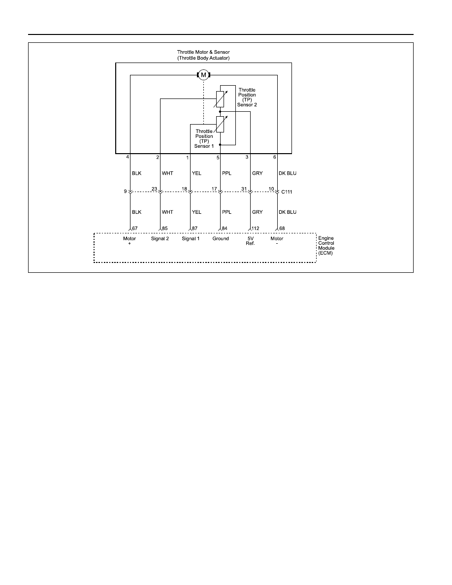
Circuit Description
The Engine Control Module (ECM) supplies a 5 volt ref
erence signal and a ground to the Throttle Position (TP)
sensor. The TP sensor sends a voltage signal back to
the ECM relative to the throttle plate opening. The volt-
age signal will vary from approximately 0.3 ~ 0.9 volts
at closed throttle, to over 4.0 ~ 4.6 volts at Wide Open
Throttle (WOT).
The TP sensors serve for engine load control according
to the drive pedal command. Load adjustments indepen-
dent of the drive pedal command can be implemented;
such functions are, for instance, idle control, speed con-
trol, drive slip control, load shock damping, and similar
functions.
When the actuator current fails, the throttle valve is re-
turned to emergency operating position by a spring. The
throttle valve position, and thereby the actuator drive
position checkback is provided by two potentiometers.
The motor positions the throttle valve against the return
spring force. Motor and return spring are two separate
energy sources. Each of them is able to position the
throttle valve in emergency position alone. Throttle valve
position checkback and monitoring is provided by two
actual value potentiometers connected to the engine
control electronics.
DIAGNOSTIC TROUBLE CODE (DTC) P0120
THROTTLE POSITION SENSORS ERROR
Conditions for Setting the DTC
•••••
Ignition ON.
•••••
Electrical system protection is not active.
Action Taken When the DTC Sets
•••••
The Malfunction Indicator Lamp (MIL) will illuminate
after two consecutive driving cycles in which the diag-
nostic runs with the fault active.
•••••
The ECM will record operating conditions at the time
the diagnostic fails. This information will be stored in
the Freeze Frame and Failure Records buffers.
•••••
A history DTC is stored.
Conditions for Clearing the MIL/DTC
•••••
The MIL will turn off after three consecutive driving
cycles in which the diagnostic runs without a fault.
•••••
A history DTC will clear after 40 consecutive warm-
up cycles without a fault.
•••••
DTC(s) can be cleared using the scan tool.
YAA1F560

ENGINE CONTROLS 1F-131
SSANGYONG Y158
Diagnostic Aids
The throttle actuator includes two potentiometers which
are supplied from the ECU. All signals are calculated
as voltage ratio (signal voltage divided by supply voltage).
This function is diagnosed continuously during ignition
on. In the following situations a fault is detected and the
system is switched to the mode of reduced operating
range:
•••••
voltage ratio of sensor 1 out of limits
•••••
voltage ratio of sensor 2 out of limits
•••••
supply voltage out of limits
•••••
voltage ratio of sensor 1 is not plausible to voltage
ratio of sensor 2
If one sensor signal is not plausible to the other one the
defective sensor is detected by checking engine speed
and air mass.
Test Description
Number(s) below refer to the step number(s) on the
Diagnostic Table.
1. The Euro On-Board Diagnostic (EOBD) System
Check prompts the technician to complete some
basic checks and store the freeze frame and failure
records data on the scan tool if applicable. This
creates an electronic copy of the data taken when
the malfuction occurred. The information is then
stored on the scan tool for later reference.
5. If DTC P0120 cannot be duplicated, the information
included in the Freeze Frame/Failure Records data
can be useful. Use the scan tool DTC information
data to determine the status of the DTC.
11. If additional DTCs are set, check the 5 reference
circuits for a short the ground.
13. If additional DTCs are set, check the 5 reference
circuits for a short the ground.
15. If the test light illuminates while probing the TP sig-
nal circuit, then the TP signal circuit is shorted to
ground.
21. The replacement ECM must be reprogrammed. Re-
fer to the latest Techline procedure for ECM repro-
gramming.
23. If no faults have been found at this point and no
additional DTCs were set, refer to “Diagnostic Aids”
in this section for additional checks and information.
1
Step
Action
Value(s)
Yes
No
DTC P0120 Throttle Position Sensor Error
2
3
4
1. Perform an Euro On-Board Diagnostic (EOBD)
System Check.
Is the system check complete?
1. Turn the ignition switch ON, with the engine OFF.
2. Install a scan tool.
3. Select the Throttle Position (TP) angle parameter on
the scan tool.
4. Monitor the scan tool while pressing the accelerator
pedal to the floor and then slowly releasing the
pedal. (Repeat the procedure several times.)
Does the TP angle value increase steadily when the
accelerator pedal is pressed to greater than the
specified value and decrease steadily when the pedal is
released to less than the specified value?
Does the scan tool display a throttle position (TP)
sensor 1 voltage between the specified value when the
throttle is fully closed?
Does the scan tool display a throttle position (TP)
sensor 2 voltage between the specified value when the
throttle is fully closed?
1. Review the Freeze Frame data and note the
parameters.
2. Operate the vehicle within the Freeze Frame
conditions and Conditions for Setting The DTC as
noted.
Is the DTC P120 set again?
5
-
Go to Step 6
Go to Step 22
4.0 - 4.6 v
Go to Step 5
Go to Step 6
0.3 - 0.9 v
Go to Step 4
Go to Step 6
98 %
1 %
Go to Step 3
Go to Step 5
-
Go to Step 2
Go to “Euro
On-Board
Diagnostic
System Check”
Нет комментариевНе стесняйтесь поделиться с нами вашим ценным мнением.
Текст