SsangYong Actyon Sports II. Manual — part 174

01-14
(7) How to end self-diagnosis
Turn the AUTO switch ON or turn OFF the ignition key.
(8) When A/C system is faulty (Initial auto-diagnosis)
The fault code for the faulty sensor is not displayed. Therefore you should start the self-diagnosis to
check the system.

01-15
6810-01
3) Trouble Diagnosis
(1) Duct Temperature Sensor
If the fault code for the duct temperature sensor (DTC 3) appears on the display, check the sensor as
follows:
Remove the duct temperature sensor and measure the resistance between the terminals of the
connector (specification: approx. 2.2 kW at 25℃). If the resistance value is extremely high or
low, replace the duct temperature sensor.
If the result is not as specified, replace the duct temperature sensor. If the result is as specified,
proceed to the next step.
Turn the ignition switch to ON position and measure the voltage between the connector of the FATC
controller and the duct temperature sensor (specification: approx. 2 V at 25℃).
If the voltage cannot be measured, check the wiring for open circuit. If the result is as specified,
replace the FATC controller.
A.
B.
C.
D.
(2) Power Transistor
If the fault code for the power transistor (DTC 6) is displayed, check as follows:
Turn the ignition switch to ON position.
Measure the voltage between the terminals of the blower motor while changing the fan speed from
the lowest level to the highest level.
The specified voltage value in each stage:
A.
B.
C.
If the voltage is out of specified value, check the wiring for open circuit. If the wiring is intact, replace
the power transistor.
D.
(3) Thermo AMP Sensor (Intake Air Sensor)
If the A/C is not turned on, check as follows:
Remove the thermo AMP and measure the voltage between the terminals no. 1 and 2 of the
connector.
Check if the voltage is approx. 12 V when the output is ON and 0 V when the output is OFF.
If the voltage value is not as specified, replace the thermo AMP. If the value is as specified, proceed
to the next step.
Turn the ignition switch to ON position and turn on the A/C by pressing the A/C button. And measure
the voltage between the terminals A12 and A11 of the FATC controller connector (specification:
approx. 12 V).
If the voltage cannot be measured, check the wiring for open circuit. If the result is not as specified,
replace the thermo AMP.
A.
B.
C.
D.
E.
01-16
(4) Sun-load sensor
Remove the sun-load sensor and measure the current between the terminals with the sensor
exposed to direct sunlight.
Measure the current again in the shade. If this value is lower than the measured value in the
sunlight, the sensor is intact.
Turn the ignition switch to the "ON" position.
Measure the voltage between the terminals of the sun sensor at the FATC connector. (approx. 2.5 V
under sunlight and approx. 4.8 V under shade)
If the voltage cannot be measured, check the wiring for open circuit. If the result is not as specified,
replace the FATC controller.
A.
B.
C.
D.
E.
01-17
6810-01
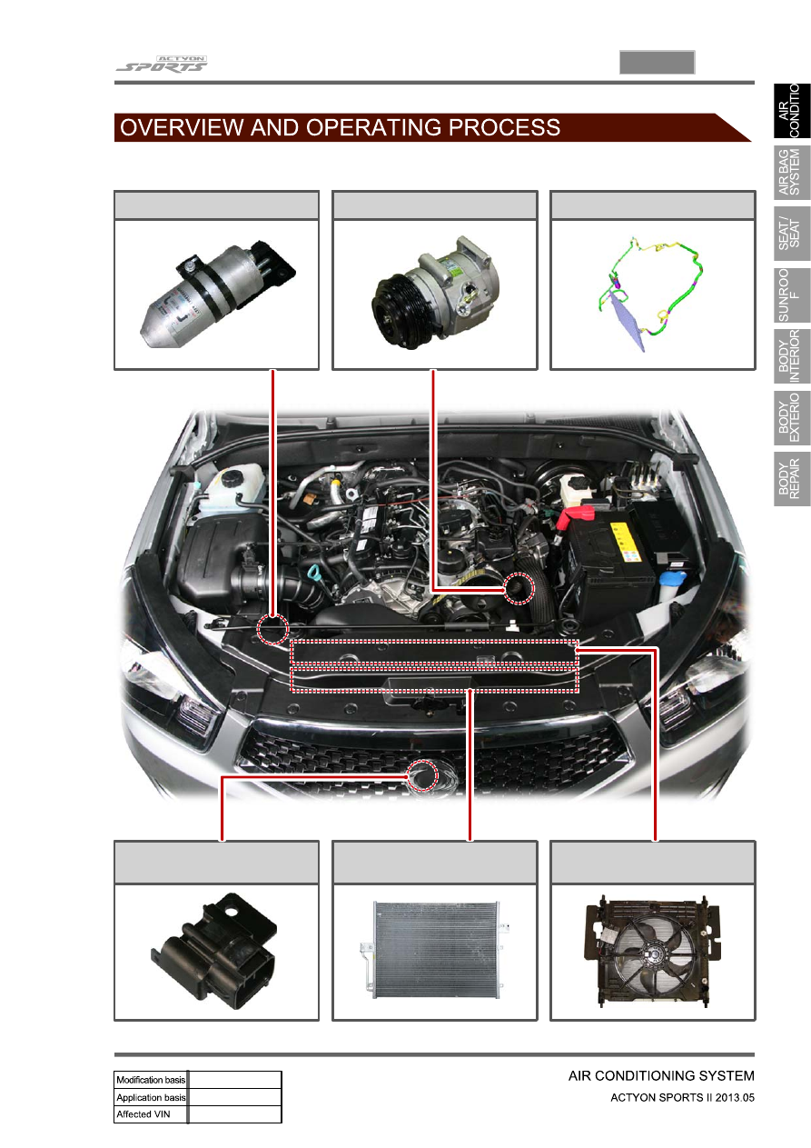
1. SYSTEM LAYOUT (EXTERIOR)
Receiver drier
A/C compressor
Line and port
Ambient temperature sensor
A/C condenser
Electric fan
Нет комментариевНе стесняйтесь поделиться с нами вашим ценным мнением.
Текст