Isuzu D-Max / Isuzu Rodeo (TFR/TFS). Manual — part 14
4JA1-TC/4JH1-TC ENGINE DRIVEABILITY AND EMISSIONS
6E–51
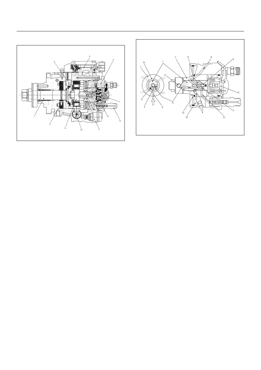
Cross-section View
(1) Drive Shaft
(2) Feed Pump
(3) Pump Camshaft Speed Sensor
(4) Pump Control Unit (PSG)
(5) Distributor Head
(6) Constant Pressure Valve (CPV) Holder
(7) High Pressure Solenoid Valve
(8) Constant Pressure Valve (CPV)
(9) Timing Control Valve (TCV)
(10) Timer
(11) Radial Plunger High Pressure Pump
(1) Rotor Shaft
(2) Radial Plunger
(3) High Pressure Passage
(4) Low Pressure Inlet
(5) Distributor Slit
(6) Valve Needle
(7) Barrel
(8) Annular Passage
(9) Fuel Return
(10) High Pressure Solenoid Valve
(11) High Pressure Outlet
(12) Diaphram Chamber
(13) Accumulator Diaphram

6E–52
4JA1-TC/4JH1-TC ENGINE DRIVEABILITY AND EMISSIONS
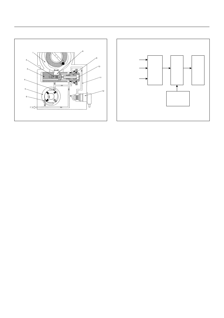
Low Pressure Fuel Circuit
The low pressure fuel circuit must supply sufficient fuel
to the high pressure fuel circuit. The main components
are the feed pump, the regulating valve and the overflow
valve.
High Pressure Fuel Circuit
In addition high pressure generating device, the high
pressure circuit also consists of fuel piping, and devices
to set the beginning of injection and fuel injection
quantity.
The main components are as follows.
• High pressure generation: Radial Plunger High
Pressure Pump
• Fuel distribution: Distributor Head
• Beginning of injection timing: Timing Device
• Prevention of secondary injection: Constant Pressure
Valve (CPV)
(1) Fuel Suction
(2) Regulating Valve
(3) Overflow Valve
(4) Feed Pump
(5) To Fuel Tank
(1) Pump Control Unit (PSG)
(2) Distributor Head
(3) High Pressure Solenoid Valve
(4) Constant Pressure Valve (CPV)
(5) Radial Plunger High Pressure Pump
4JA1-TC/4JH1-TC ENGINE DRIVEABILITY AND EMISSIONS
6E–53
Timing Control
The timing device determines the optimum injection
timing against variations in engine speed.
The pressure of the fuel fed from the feed pump is
adjusted in accordance with speed by the regulating
valve. This delivery pressure acts on the hydraulic
stopper's annular chamber as control pressure.
The chamber pressure of the annular chamber is
controlled by the timing control valve (TCV).
The timing plunger is connected to the cam ring by a
ball pin. Axial movement of the timing plunger is
transferred to the cam ring in the form of rotational
movement. Movement to the right of the timing plunger
(to the spring side) advances injection timing.
The main components are timing plunger, the timing
control valve (TCV) and pump camshaft speed sensor.
Start of Injection
The engine control module (ECM) contains
characteristic maps of the beginning of injection,
corresponding to engine operating conditions (engine
load, engine speed and engine coolant temperature).
The pump control unit (PSG) is constantly comparing
the set beginning of injection timing and the actual
beginning of injection timing.
If there is a difference, the timing control valve (TCV) is
controlled by the duty ratio. (The actual beginning of
injection timing is determined from the pump camshaft
speed sensor.)
(1) Cam Ring
(2) Servo Valve
(3) Timer Piston
(4) Outlet
(5) Feed Pump
(6) Inlet
(7) Fuel Suction
(8) Ball Pin
(9) Annular Chamber
(10) Hydraulic Stopper
(11) Return Passage
(12) Timing Control Valve (TCV)
Engine Load
Engine Speed
Engine Coolant
Temperature
Engine
Control
Module
(ECM)
Pump
Control
Unit
(PSG)
Pump
Camshaft
Speed Sensor
Timing
Control
Valve
(TCV)
6E–54
4JA1-TC/4JH1-TC ENGINE DRIVEABILITY AND EMISSIONS
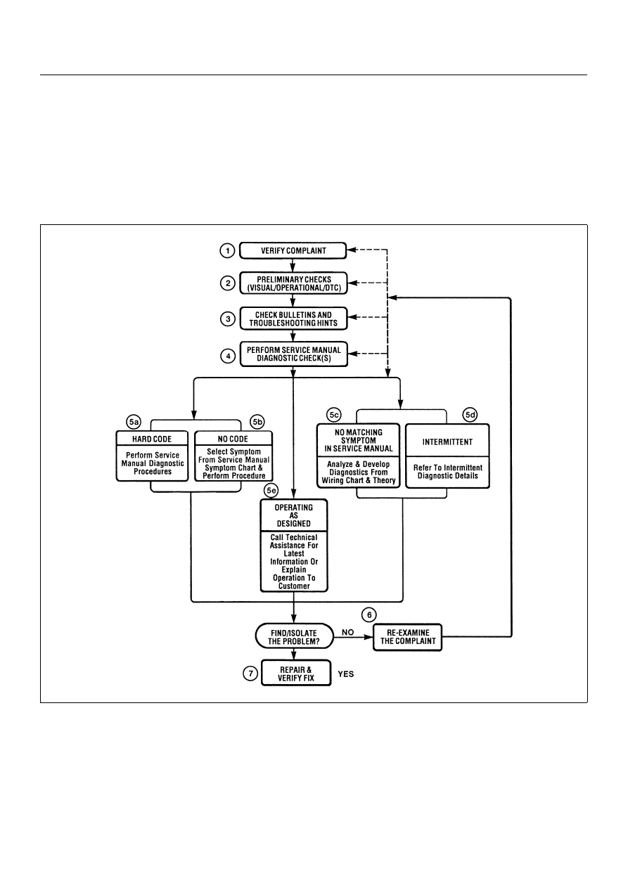
ISUZU Strategy Based Diagnostics
Overview
As a retail service technician, you are part of the ISUZU
service team. The team goal is FIX IT RIGHT THE
FIRST TIME for the satisfaction of every customer. You
are a very important member of the team as you
diagnose and repair customer vehicles.
You have maximum efficiency in diagnosis when you
have an effective, organized plan for your work. Strategy
Based Diagnostics (refer to Figure 1) provides you with
guidance as you create and follow a plan of action for
each specific diagnostic situation.
STRATEGY BASED DIAGNOSTICS CHART
Нет комментариевНе стесняйтесь поделиться с нами вашим ценным мнением.
Текст