Isuzu D-Max / Isuzu Rodeo (TFR/TFS). Manual — part 662
7A1 – 148 AUTOMATIC TRANSMISSION (4L30-E)
INSTALLATION
To install, follow the removal steps in the reverse order,
noting the following points;
1. Mode Switch Bolt Torque
N·m (kg·cm / lb·in)
13 (130 / 113)
Selector Lever Nut Torque
N·m (kg·m / lb·ft)
23 (2.3 / 17)
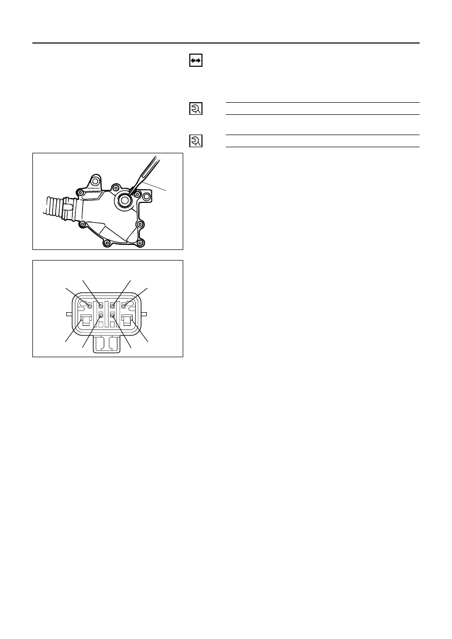
2. Mode switch setting procedure
Perform either of the following adjustment
procedures:
Procedure1
a. Place selector lever in neutral.
b. Remove selector lever from the mode switch.
c.
Remove the mode switch cover.
d. Loosen the two 10 mm screws.
e. Rotate the mode switch until the slot in the mode
switch housing aligns with the selector shaft
bushing, and insert a 3/32 in. (2.4 mm) drill bit or
punch (1) into the slot.
f.
Tighten the screws to 13 N·m (113 lb·in).
g. After completing adjustment, snap the mode
switch cover into place.
h. Reinstall the selector lever.
Procedure2
a. Place selector lever in neutral.
b. Disconnect transmission harness connector from
mode switch connector.
c.
Remove mode switch connector with bracket
from the transmission case.
d. Connect multimeter (resistance mode) to
terminals 1(E) and 4(H) on mode switch
connector.
e. Loosen two mounting screws.
f.
Rotate mode switch slightly in both directions to
determine the range (approx. 5 degrees) of
electrical contact.
g. Position mode switch in middle of contact range.
h. Tighten two mounting screws.
I.
Remove multimeter and install mode switch
harness connector with bracket to the
transmission case.
j.
Connect transmission harness connector to mode
switch connector.
1
249RW001
Mode switch connector
5 (D)
8 (A)
6 (C)
3 (G)
4 (H)
7 (B)
2 (F)
1 (E)
F07RW003
AUTOMATIC TRANSMISSION (4L30-E) 7A1 – 149
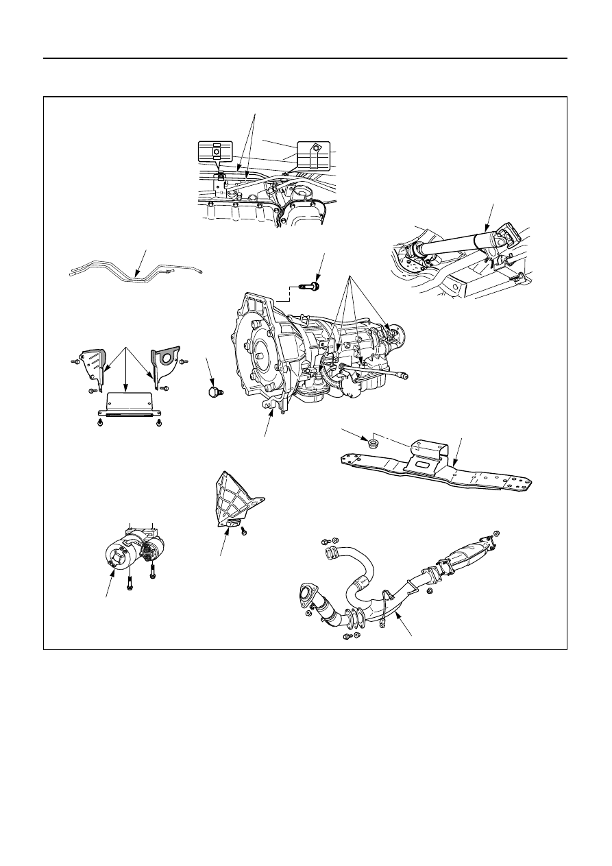
4
3
12
13
6
8
11
10
9
7
5
1
2
TRANSMISSION
240LW002
Removal Steps
1. Exhaust pipe
2. Rear propeller shaft
3. Fuel pipe
4. ATF oil cooler pipe
5. Heat protector
6. Harness connector
7. Starter
8. Flywheel under cover
9. Flywheel-Torque converter bolt
10. Rear mount nut
11. 3rd crossmember
12. Engine-transmission bolt
13. Transmission assembly
Installation Steps
To install, follow the removal steps in the
reverse order.

7A1 – 150 AUTOMATIC TRANSMISSION (4L30-E)
REMOVAL
Preparation:
•
Remove engine hood.
•
Disconnect negative (–) battery cable.
1. Exhaust Pipe
1) Remove catalytic converter, center pipe and left
front pipe.
2) Disconnect O
2
sensor connector from the
transmission harness connector.
2) Disconnect rear propeller shaft transmission side.
2. Rear Propeller Shaft
1) Disconnect shift control rod from the selector
lever assembly side.
3. Fuel Pipe
Disconnect two fuel pipe clamp bracket from the
transmission case eight side.
4. ATF Oil Cooler Pipe
1) Disconnect ATF oil cooler pipe from transmission
side.
2) Remove oil pipe clamp bracket from torque
converter case.
3) Loosen oil pipe clamp bolt at the engine mount
side.
256LW004
401LW001
141LW001
253LW002
AUTOMATIC TRANSMISSION (4L30-E) 7A1 – 151
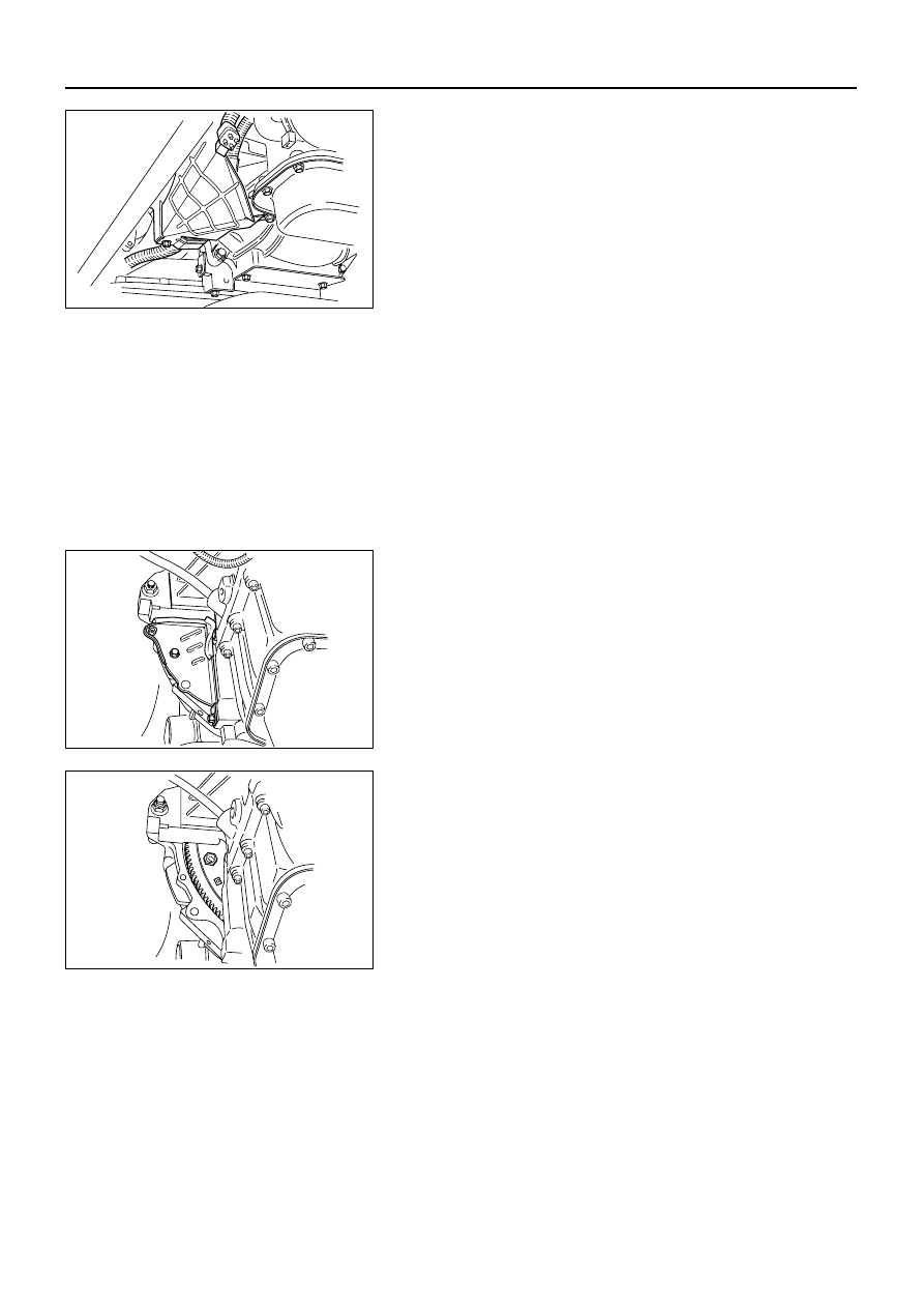
5. Heat Protector
6. Harness Connector
1) Disconnect transmission harness connectors from
transmission side connectors.
2) Disconnect harness clamp from transmission case
side.
7. Starter
8. Flywheel Under Cover
Remove flywheel under covers (3 pieces) from
transmission case.
9. Flywheel – Torque Converter Bolt
Remove flywheel torque converter fixing bolts (6
pieces) by turning crankshaft.
10. Rear Mount Nut
1) Support transmission with a jack.
2) Remove two rear mount nuts from the rear
mount.
11. 3rd Crossmember
Remove eight 3rd crossmember bolts.
12. Engine-Transmission Bolt
1) Hoist engine with a chain block.
2) Remove engine-transmission bolts
13. Transmission Assembly
815LW001
210LW001
210LW002
Нет комментариевНе стесняйтесь поделиться с нами вашим ценным мнением.
Текст