Isuzu D-Max / Isuzu Rodeo (TFR/TFS). Manual — part 663
7A1 – 152 AUTOMATIC TRANSMISSION (4L30-E)
INSTALLATION
To install, follow the removal steps in the reverse order,
noting the following points;
13. Transmission Assembly
Slowly raise transmission jack until front of the
transmission is aligned with rear of the engine.
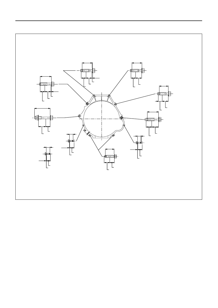
12. Engine-Transmission Bolt
Tighten engine-transmission bolts, to the specified
torque (see next page).
11. 3rd Crossmember
3rd Crossmember Bolt Torque
N·m (kg·m / lb·ft)
50 (5.1 / 37)
10
Rear Mount Nut
Rear Mount Nut Torque
N·m (kg·m / lb·ft)
41 (4.2 / 30)
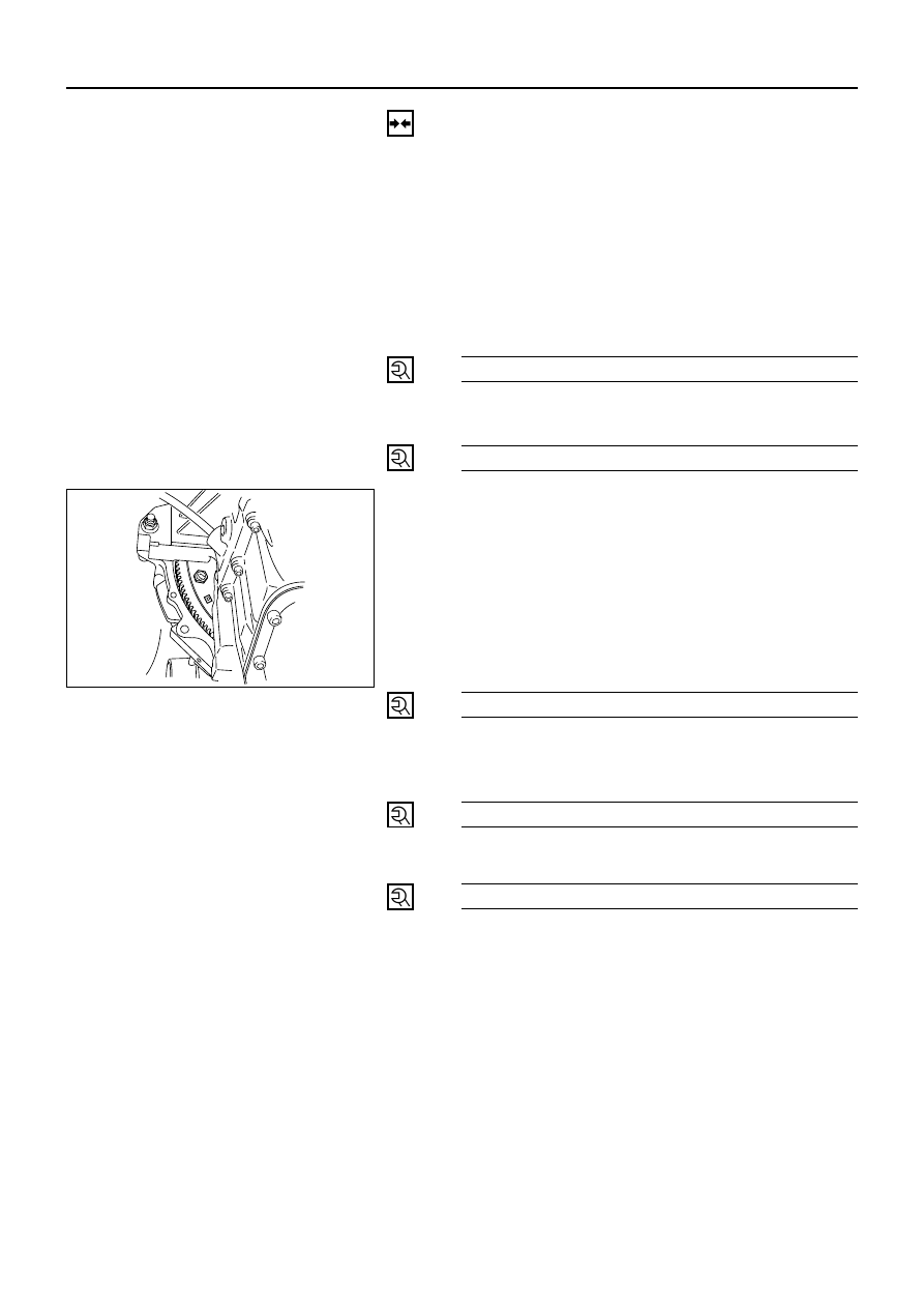
9. Flywheel-Torque Converter Bolt
1) Align the flywheel-torque converter bolt boss with
the starter portion of the converter housing by
turning torque converter.
2) Install new flywheel-torque converter bolts (6
pieces) by turning crankshaft.
NOTE:
Do not reuse the flywheel-torque converter bolt.
Flywheel-Torque Converter
Bolt Torque
N·m (kg·m / lb·ft)
55 (5.6 / 41)
8. Flywheel Under Cover
Flywheel Under Cover
Bolt Torque
N·m (kg·cm / lb·in)
8 (80 / 69)
7. Starter
Starter Bolt Torque
N·m (kg·m / lb·ft)
40 (4.1 / 30)
6. Harness Connector
1) Connect transmission harness connectors to
transmission side.
2) Connect harness clamp to transmission harness
clamp bracket.
210LW002
AUTOMATIC TRANSMISSION (4L30-E) 7A1 – 153
(6places)
Cylinder block
T/M case
Bracket;fuel pipe
Clip;breather hose
Cylinder block
T/M case
Under cover
Crank case
45
50
21 27
2.5
76(7.7/56)
76(7.7/56)
8(0.8/69lb in)
8(0.8/69lb in)
8(0.8/69lb in)
40(4.1/30)
76(7.7/56)
76(7.7/56)
76(7.7/56)
76(7.7/56)
Torque : N•m(kg•m/lb ft)
Length : mm
70
32 20
Cylinder block
T/M case
21 27
1.2
45
Cylinder block
T/M case
21 27
40
40
50
10
Cylinder block
T/M case
17 27
Cylinder block
T/M case
25
30
Crank case
T/M case
25 20
T/M case
0.9
20
Under cover
10
T/M case
0.9
20
Under cover
10
0.9
11
Engine-Transmission Bolt Torque
F07RW041

7A1 – 154 AUTOMATIC TRANSMISSION (4L30-E)
5. Heat Protector
Heater Protector Bolt Torque
N·m (kg·cm / lb·in)
6 (60 / 52)
4. ATF Oil Cooler Pipe
1) Install ATF oil cooler pipe to transmission.
ATF Oil Cooler Pipe Nut Torque
N·m (kg·m / lb·ft)
54 (5.5 / 40)
2) Install oil pipe clamp bracket to torque converter
case.
3) Tighten oil pipe clamp bolt at engine mount side.
3. Fuel Pipe
Connect fuel pipe bracket to transmission side.
2. Rear Propeller Shaft
Connect shift control rod to the selector lever assembly.
Propeller Shaft Bolt Torque
N·m (kg·m / lb·ft)
63 (6.4 / 46)
1. Exhaust Pipe
Exhaust Pipe Bolt Torque
N·m (kg·m / lb·ft)
Exh. pipe to exh. manifold
67 (6.8 / 49)
Exh. pipe flange bolt
43 (4.4 / 32)
Connect O
2
sensor connector to transmission harness
connector.
815LW001
253LW002
141LW001
AUTOMATIC TRANSMISSION (4L30-E) 7A1 – 155
SOLENOID VALVE
(MAIN CASE VALVE BODY)
REMOVAL
Preparation:
•
Disconnect negative (–) battery cable.
•
Drain fluid.
Refer to “SERVICING” of the SERVICE
INFORMATION (Section 00).
•
Remove exhaust pipe and disconnect oxygen
sensor connector.
•
Support transmission case with a jack and remove
third crossmember.
1. Main Case Oil Pan
Remove sixteen 10 mm screws, main case oil pan,
magnet, and gasket.
2. Oil Filter
Remove three 13 mm screws, oil filter.
3. Wiring Harness
Disconnect wiring harness from band control
solenoid, shift solenoids. Pull only on connectors, not
on wiring harness.
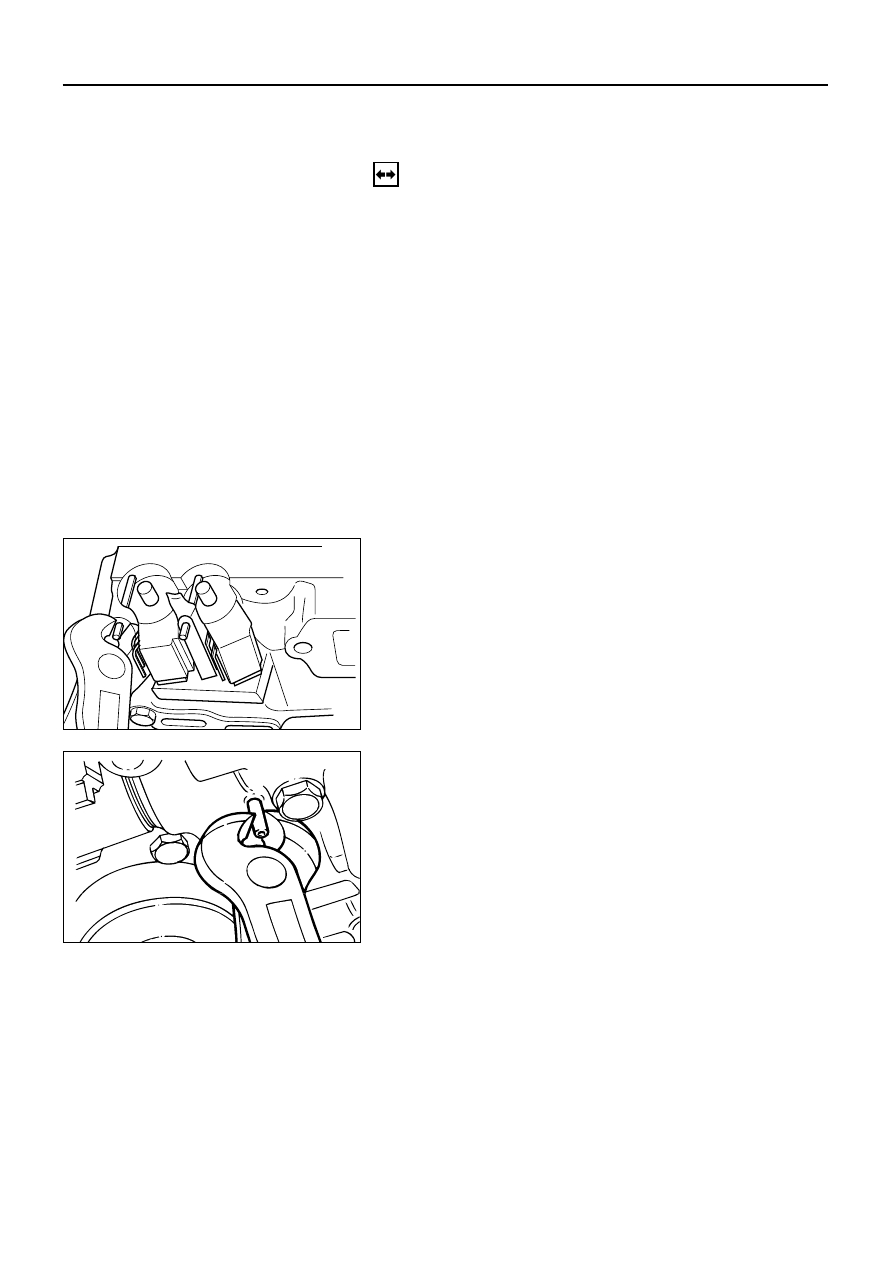
4. Spring Pin
Remove spring pin for shift solenoid A, shift solenoid
B, and band control solenoid respectively, using
suitable pliers taking care not to damage solenoids.
5. Solenoids
Remove shift solenoid A, shift solenoid B, band
control solenoid, and gaskets from main case valve
body. Do not pull on wiring harness. Remove
solenoids by grasping the metal tip.
210RW010
244RW003
Нет комментариевНе стесняйтесь поделиться с нами вашим ценным мнением.
Текст