Isuzu D-Max / Isuzu Rodeo (TFR/TFS). Manual — part 1985
STEERING 3B-19
Turn the ignition/starter key to OFF position.
Note :
With the steering in lock position, the steering lock
assembly cannot be removed.
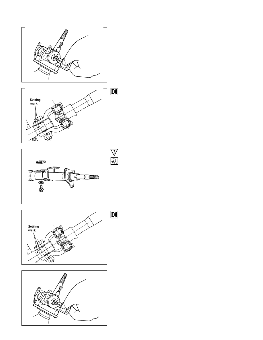
9. Steering Column Assembly
Apply a setting mark across the universal joint and steering
shaft to reassemble of the parts in their original position.
Note :
A Setting mark can be easily punched if the shaft is
withdrawn a little by loosening the steering shaft universal
joint.
Important Operations - Installation
9. Steering Column Assembly
Steering Column Torque
N
⋅m (kgf⋅m/Ib⋅ft)
16.7
±2.0 (1.7±0.2/12.3±1.4)
Align the setting marks made when removing.
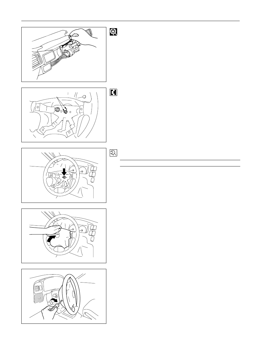
8. Steering Lock and Bearing
Turn the ignition/starter key to OFF position.
With the steering in lock position, the steering lock assembly
cannot be installed.
3B-20 STEERING
Install the steering lock assembly using the inner hex wrench.
Setting mark
3., 3a. Steering Wheel
(1) Align the setting marks made when removing.
(2) Apply grease to contact ring.
Note :
Never apply blow to the setting wheel in direction of the
shaft by using a hammer or other impact tools in an
attempt to install the steering wheel, the setting shaft is
designed as an energy absorbing unit.
2., 2a. Nut
Steering Wheel Nut Torque
N
⋅m (kgf⋅m/Ib⋅ft)
34.3
±4.9 (3.5±0.5/25.3±3.6)
1. Horn shroud
(1) Remove the bracket from the nail at the lower side of pad
assembly with a screw driver.
(2) Install the bracket (removed at procedure 1) onto the
steering wheel sub assembly with a screw.
(3) Connect the harnesses, then, hang the nail of the pad
assembly onto the plate of the steering wheel sub
assembly, and install the pad carefully so that the nail is not
separated from the bracket. (See the lowest figure.)
STEERING 3B-21
STEERING UNIT
GENERAL DESCRIPTION
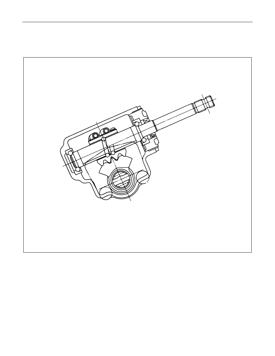
MANUAL STEERING UNIT
The steering gear is mainly comprised of the sector gear and the worm nut assembly.
There are many recirculating balls installed to the ball groove (way) between the worm nut and the steering worm
shaft.
The steering gear's high mechanical efficiency provides very light steering.
Racks machined into the worm nut side face engage the fan shaped sector gear to transfer the steering wheel
applied torque to the pitman arm.
3B-22 STEERING
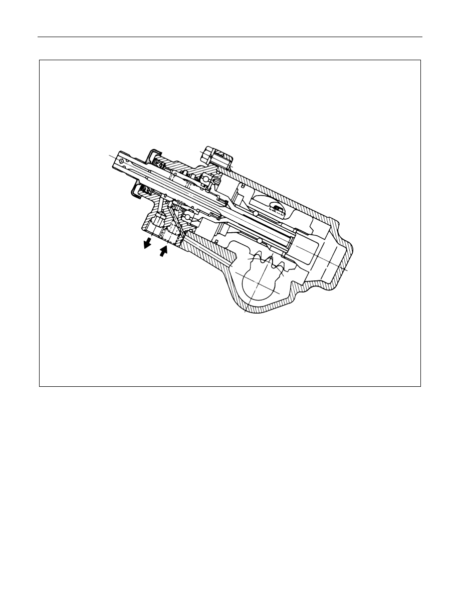
POWER STEERING UNIT
Power steering is designed to reduce the steering wheel turning effort by utilizing hydraulic pressure to bolster the
normal torque developed by the steering wheel box.
The power steering unit incorporates a power piston and sector shaft as an integral part of the steering gear. A
control valve is built into the steering housing.
Because the tire rolling resistance is constantly applied to the worm shaft, the torsion bar twists with the Steering
Wheel. As the torsion bar twists, the relative torque displacement between the worm shaft and the rotor changes.
An equivalent oil pressure is applied to the piston to bolster the normal torque.
Нет комментариевНе стесняйтесь поделиться с нами вашим ценным мнением.
Текст