Isuzu D-Max / Isuzu Rodeo (TFR/TFS). Manual — part 1984

STEERING 3B-15
STEERING MECHANISM
GENERAL DESCRIPTION
STEERING MECHANISM
3B-16 STEERING
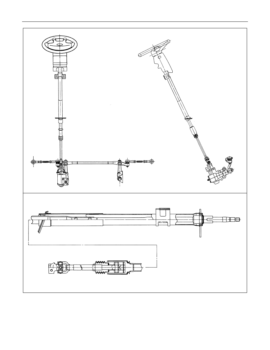
The steering mechanism comprises a steering wheel, steering column, steering shaft, steering unit, and steering
linkage.
The steering shaft is equipped with slid joints to prevent vehicle vibration from transferring to the steering wheel.
STEERING 3B-17
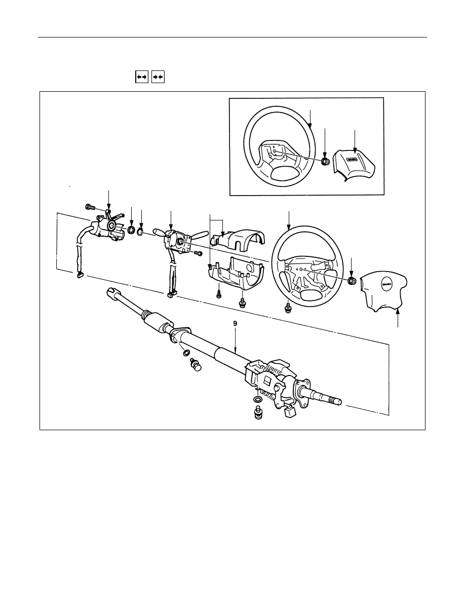
STEERING COLUMN
REMOVAL AND INSTALLATION
8
3a
2a
1a
7
6
5
4
3
2
1
Removal Steps
! 1., 1a. Horn shroud
2., 2a. Nut
! 3., 3a.Steering wheel
4. Steering cowl
5. Combination switch
6. Snap ring
7. Bushing
! 8. Steering lock and bearing
! 9. Steering column assembly
Installation Steps
! 9. Steering column assembly
! 8. Steering lock and bearing
7. Bushing
6. Snap ring
5. Combination switch
4. Steering cowl
! 3., 3a. Steering wheel
! 2., 2a. Nut
! 1., 1a. Horn shroud

3B-18 STEERING
Important Operations - Removal
1., 1a. Horn Shroud
(1) Remove the arrowed screw at the rear side of the steering
wheel.
(2) Pull up the pad along the direction shown in the left figure
and remove from the steering wheel.
Setting mark
3., 3a. Steering Wheel
(1) Apply a setting mark across the steering wheel and shaft so
parts can be reassembled in their original position.
5-8521-0016-0
(2) Steering Wheel Puller : 5-8521-0016-0
(J-29752)
Note :
Never apply blow to the setting wheel in direction of the
shaft by using a hammer or other impact tools in an
attempt to remove the steering wheel, the setting shaft is
designed as an energy absorbing unit.
8. Steering Lock and Bearing
Remove the steering lock assembly using the inner hex
wrench.
Нет комментариевНе стесняйтесь поделиться с нами вашим ценным мнением.
Текст