Isuzu D-Max / Isuzu Rodeo (TFR/TFS). Manual — part 1126
ELECTRICAL-BODY AND CHASSIS 8-261
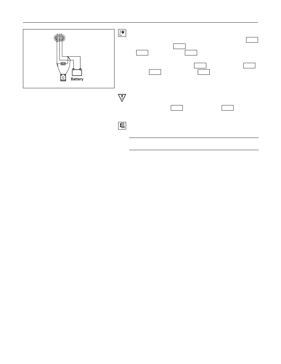
Vehicle Speed Sensor Inspection
1. Connect the vehicle speed sensor connector 1
M-10
(Diesel engine: 1
E-44
) to the battery (+) terminal and 2
M-10
(Diesel engine: 2
E-44
) to the (-) terminal.
2. Connect a resistance of 1.3K ohm to 5K ohm (1/4 W or
more) between connectors 1
M-10
. (Diesel engine: 1
E-44
)
and 3
M-10
(Diesel engine: 3
E-44
)
CAUTION:
Be extremely careful not to connect the battery (+) terminal
to the connector 3
M-10
(Diesel engine: 3
E-44
).
This may damage the vehicle speed sensor.
3. Rotate the shaft of the vehicle speed sensor slowly and
measure the voltage at the both ends with a digital tester.
The voltage, with one rotation of shaft fluctuates four times in
the following range: 10 to 14V - 2V or less.
8-262 ELECTRICAL-BODY AND CHASSIS
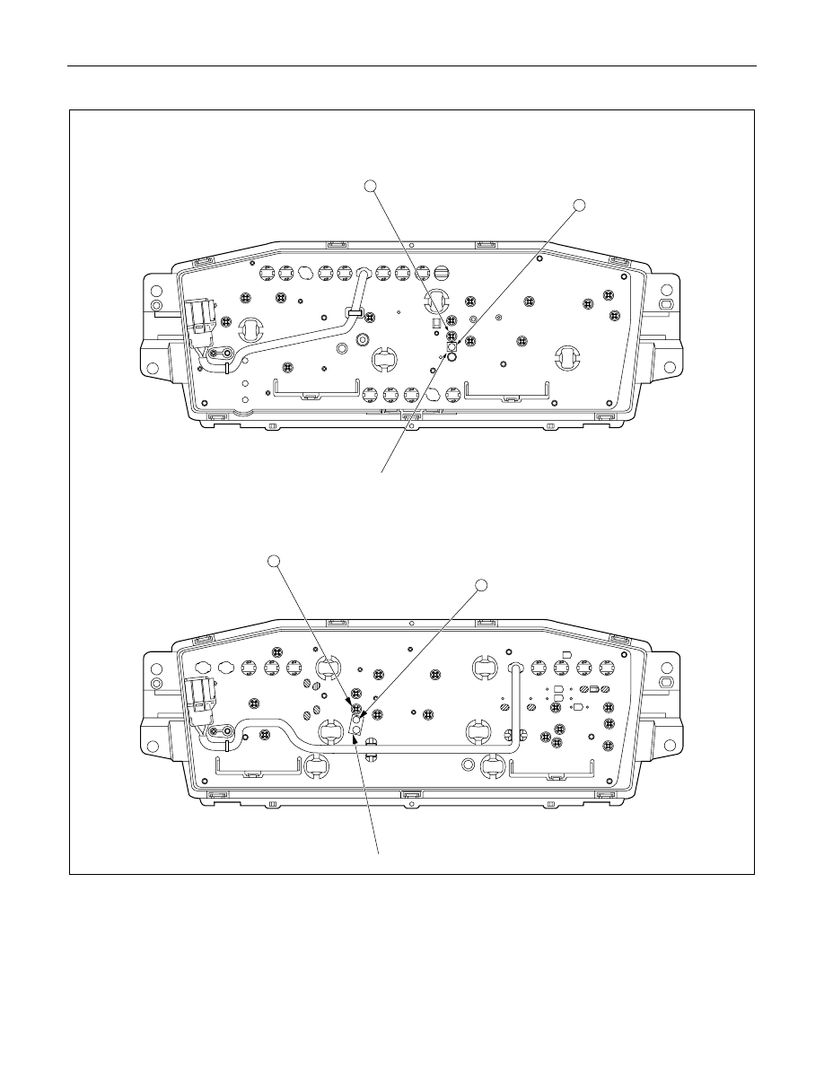
Timing Belt Indicator Light Reset Procedure (4 Diesel Engine)
Masking tape
A
B
W/ Tachometer
Masking tape
W/O Tachometer
A
B
Timing belt must be replaced after 100,000 km of vehicle operation.
When the odometer reading reaches 100,000 km, the timing belt indicator light will turn on to remind the driver to
change the timing belt.
After replacing the timing belt, the timing belt indicator light must be reset to remind the driver to replace the timing
belt after the next 100,000 km.

ELECTRICAL-BODY AND CHASSIS 8-263
Timing Belt Indicator Light Reset Procedure
1. Remove the masking tape from the hole
B
.
2. Remove the screw from the hole
A
and install it to the hole
B
.
3. Apply new masking tape to the hole
A
.
Note:
The above procedure assumes that the timing belt is being
replaced for the first time (after 100,000 km).
For subsequent reset procedure (at next 100,000 km), hole
positions will be the opposite of the above procedure.
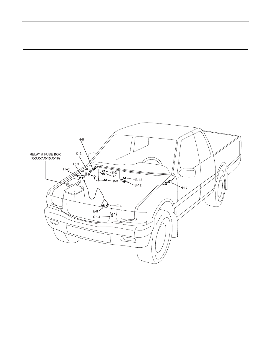
8-264 ELECTRICAL-BODY AND CHASSIS
HEATER AND AIR CONDITIONING
PARTS LOCATION (LHD EXCEPT EC)
Нет комментариевНе стесняйтесь поделиться с нами вашим ценным мнением.
Текст