Isuzu D-Max / Isuzu Rodeo (TFR/TFS). Manual — part 1776
DIAGNOSIS 7A2-155
DIAGNOSIS 7A2-156
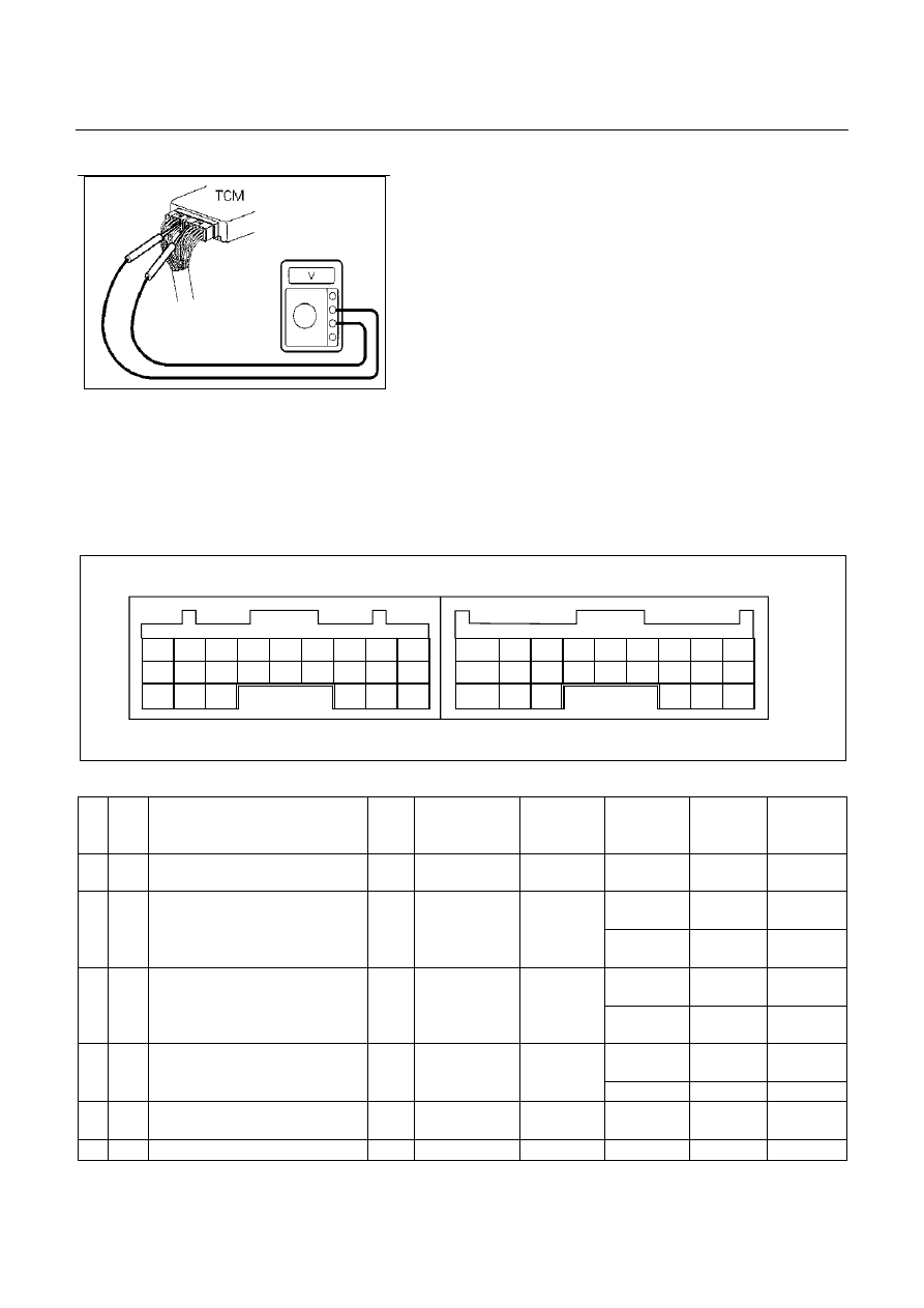
TCM VOLTAGE CHECK
TCM voltage check is done to check for transmission and TCM
problems which cannot be detected by self-diagnosis.
Additionally, it severs as a back-up check for self-diagnosis.
Measure the voltage drop and make a continuity test for each of
sensors, solenoids and switches.
If the voltage is within the specified range and continuity exists,
that particular area of the TCM and transmission assembly is
normal.
If voltage deviation or lack of continuity is discovered, disconnect
the applicable parts and check of them individually.
Inspection Tool
Use a circuit tester and an oscilloscope to measure voltage and
circuit continuity.
Insert the test probes from the connector wiring side. TCM
terminals are extremely small.
Wrap a piece of thin wire around the probe of tester.
This will make measurement easier.
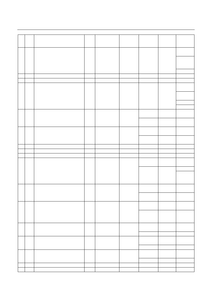
TCM Pin Assignment
Connect to White Connector Connect to Grey Connector
No.
Wire
Color
Pin Name
Input /
Output
Connected to
Measurement
Item
Measurement
Condition
Standard
Inspection
Point at
Trouble
A1
RED
V BATT (Battery Back-up Power
Supply)
Input
Battery Voltage
-
Battery
voltage
Related
harness
At P range
Battery
voltage
Related
harness
A2
YEL/
VIO
P Range Switch
Input
Inhibitor switch
Voltage
At other than
P range
Less than 2V
Inhibitor
switch
At brake
stepped
Battery
voltage
Related
harness
A3
RED Brake
Switch
Input
Brake
switch
Voltage
At brake no
stepped
Less than 2V Brake switch
At lamp OFF
Battery
voltage
Related
harness
A4
PNK/
WHT
3rd Start Indicator Lamp
Output 3rd start lamp
Voltage
At lamp ON
Less than 2V Lamp
A5
GRN
K-line signal (Tech 2 serial
communication)
Input/
Output
Tech 2
-
-
-
Related
harness
A6
- -
- -
-
-
-
-
DIAGNOSIS 7A2-157
No.
Wire
Color
Pin Name
Input /
Output
Connected to
Measurement
Item
Measurement
Condition
Standard
Inspection
Point at
Trouble
Related
harness
Engine
Speed
Sensor
A7
BLK/
RED
Engine Speed Sensor
Input
ECM
Voltage (Wave
form)
At 1500rpm.
Circuit tester
(+) to A7 pin,
(-) to B5 pin.
Pulse
generated
(At AC range
approx. 5.5
V)
ECM
A8
- -
- -
-
-
-
-
A9
- -
- -
-
-
-
-
Related
harness
Speed
sensor
Speed meter
A10
BLK/
YEL
Vehicle Speed Sensor Out (2WD Only) Output Speed meter
Voltage (Wave
form)
At run in L
range in 1st
gear 20 km/h.
Circuit tester
(+) to A10 pin,
(-) to B5 pin.
Pulse
generated
(At AC range
approx. 6.5
V)
TCM
At switch
pushed
Less than 2V
Related
harness
A11
GRN/
WHT
3rd Start Select Switch
Input
3rd start switch
Voltage
At switch off
Battery
voltage
3rd start
switch
At 4L
Less than 2V
Related
harness
A12
BLU/
WHT
4L Mode Switch (4WD Only)
Input
Transfer control
unit
Voltage
At other than
4L
Battery
voltage
4L switch
A13
- -
- -
-
-
-
-
A14
- -
- -
-
-
-
-
A15
- -
- -
-
-
-
-
At fully close
Off duty 10%
Related
harness
ECM
A16
RED/
WHT
Throttle Position Sensor
Input
ECM
Wave form
(140Hz Duty
signal) *1
At fully open
Off duty 90%
Throttle
position
sensor
At 3 range
Battery
voltage
Related
harness
A17
BLK/
GRN
3 Range Switch
Input
Inhibitor switch
Voltage
At other than
3 range
Less than 2V
Inhibitor
switch
At key switch
ON
Battery
voltage
Related
harness
A18
YEL/
BLK
DIAG Switch
Input
Data link
connector
Voltage
At short circuit
of DIAG
switch
Less than 2V
At lamp OFF
Battery
voltage
Related
harness
A19
ORG/
BLU
A/T OIL TEMP Indicator Lamp
Output
AT OIL TEMP
indicator lamp
Voltage
At lamp ON
Less than 2V Lamp
At lamp OFF
Battery
voltage
Related
harness
A20
GRN/
YEL
CHECK TRANS Indicator Lamp
Output
CHECK TRANS
indicator Lamp
Voltage
At lamp ON
Less than 2V Lamp
At lamp OFF
Battery
voltage
Related
harness
A21
PNK POWER DRIVE Indicator Lamp
Output
POWER DRIVE
indicator lamp
Voltage
At lamp ON
Less than 2V Lamp
A22
- -
- -
-
-
-
-
A23
- -
- -
-
-
-
-

DIAGNOSIS 7A2-158
No.
Wire
Color
Pin Name
Input /
Output
Connected to
Measurement
Item
Measurement
Condition
Standard
Inspection
Point at
Trouble
At lamp OFF
Battery
voltage
Related
harness
A24
GRN/
YEL
Power Drive Select Switch
Input
Power drive
switch
Voltage
At lamp ON
Less than 2V Lamp
At other than
2nd or 4th
gear
More than 10
V
Related
harness
B1
RED/
YEL
2-4 Brake Pressure Switch
Input
2-4 brake
pressure switch
Voltage
At 2nd or 4th
gear
Less than 2V
Pressure
switch
At 2 range
Battery
voltage
Related
harness
B2
PNK/
BLK
2 Range Switch
Input
Inhibitor switch
Voltage
At other than
2 range
Less than 2V
Inhibitor
switch
Input
Related
harness
B3
BRN/
RED
Turbine Sensor
Turbine sensor
Voltage (Wave
form)
At run in L
range in 1st
gear 20 km/h.
Circuit tester
(+) to B3 pin,
(-) to B5 pin.
Pulse
generated
(At AC range
approx. 6.2
V)
Turbine
sensor
ATF temp.
20
°
C
Approx. 1.55
V
Related
harness
B4
BLU ATF
Thermo
Sensor
Input
ATF thermo
sensor
Voltage
ATF temp.
60
°
C
Approx. 0,7V
Thermo
sensor
B5
BLK Ground
-
Ground
Voltage
Normally
Less than 2V
Related
harness
Related
harness
B6
BLU/
BLK
Low & Reverse Brake Duty Solenoid
Output
Low & reverse
brake duty
solenoid
Voltage (Wave
form)
P, N range.
Circuit tester
(+) to B6 pin,
(-) to B22 pin.
Pulse
generated
(At AC range
approx.
6.8V)
Duty solenoid
Related
harness
B7
BLK/
YEL
2-4 Brake Duty Solenoid
Output
2-4 brake duty
solenoid
Voltage (Wave
form)
P, N range.
Circuit tester
(+) to B7 pin,
(-) to B22 pin.
Pulse
generated
(At AC range
approx.
6.8V)
Duty solenoid
Related
harness
B8
RED High Clutch Duty Solenoid
Output
High clutch duty
solenoid
Voltage (Wave
form)
P, N range.
Circuit tester
(+) to B8 pin,
(-) to B22 pin.
Pulse
generated
(At AC range
approx.
6.8V)
Duty solenoid
Related
harness
B9
WHT/
RED
Low Clutch Duty Solenoid
Output
Low clutch duty
solenoid
Voltage (Wave
form)
4th gear in D
range. Circuit
tester (+) to
B9 pin, (-) to
B22 pin.
Pulse
generated
(At AC range
approx.
6.8V)
Duty solenoid
At N range
Battery
voltage
Related
harness
B10
RED/
BLK
N Range Switch
Input
Inhibitor switch
Voltage
At other than
N range
Less than 2V
Inhibitor
switch
At D range
Battery
voltage
Related
harness
B11
BLU D Range Switch
Input
Inhibitor switch
Voltage
At other than
D range
Less than 2V
Inhibitor
switch
Нет комментариевНе стесняйтесь поделиться с нами вашим ценным мнением.
Текст