Isuzu D-Max / Isuzu Rodeo (TFR/TFS). Manual — part 1777
DIAGNOSIS 7A2-159
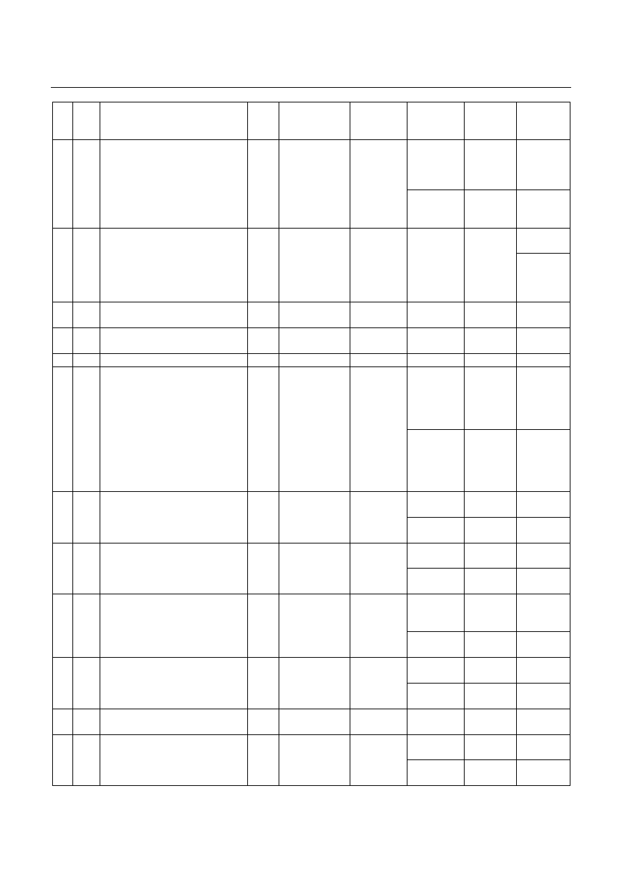
No.
Wire
Color
Pin Name
Input /
Output
Connected to
Measurement
Item
Measurement
Condition
Standard
Inspection
Point at
Trouble
At other than
R range, L
range 1st
gear
More than 10
V
Related
harness
B12
YEL Low & Reverse Brake Pressure Switch
Input
Low & reverse
brake pressure
switch
Voltage
At R range, L
range 1st
gear
Less than 2V
Pressure
switch
Related
harness
B13
YEL/
RED
Vehicle Speed Sensor
Input
Vehicle speed
sensor
Voltage (Wave
form)
At run in L
range in 1 st
gear 20 km/h.
Circuit tester
(+) to B13 pin,
(-) to B5 pin.
Pulse
generated
(At AC range
approx. 6.2
V)
Vehicle
speed
sensor
B14
BLU/
BLK
ATF Thermo Sensor Ground
-
ATF thermo
sensor
Continuity Normally
Continuity
Related
harness
B15
BLK Ground
-
Ground
Voltage
Normally
Less than 2V
Related
harness
B16
- -
- -
-
-
-
-
At lock-up.
Circuit tester
(+) to B17 pin,
(-) to B5 pin.
Pulse
generated
(At AC range
approx. 7.2
V)
Related
harness
B17
BLK Lock-up Duty Solenoid
Output
Lock-up duty
solenoid
Voltage (Wave
form)
At unlock-up.
Circuit tester
(+) to B17 pin,
(-) to B5 pin.
Pulse
generated
(At AC range
approx. 4.0
V)
Duty solenoid
At key switch
ON
Battery
voltage
Related
harness
B18
WHT V ign (Ignition Power Supply)
Input
Key switch
Voltage
At key switch
OFF
Less than 2V Fuse
At R range
Battery
voltage
Related
harness
B19
RED/
YEL
R Range Switch
Input
Inhibitor switch
Voltage
At other than
R range
Less than 2V
Inhibitor
switch
At other than
3rd or 4th
gear
More than 10
V
Related
harness
B20
WHT/
BLK
High Clutch Oil Pressure Switch
Input
High clutch
pressure switch
Voltage
At 3rd or 4th
gear
Less than 2V
Pressure
switch
At L range
Battery
voltage
Related
harness
B21
PNK/
BLK
L Range Switch
Input
Inhibitor switch
Voltage
At other than
L range
Less than 2V
Inhibitor
switch
B22
GRY/
RED
Ground Return
Output Shift solenoid
Continuity
Normally
Continuity
Related
harness
At N range
Battery
voltage
Related
harness
B23
VIO Line
Pressure
Solenoid
Output
Line pressure
solenoid
Voltage
At D range
stall
Less than 2V Solenoid
DIAGNOSIS 7A2-160
No.
Wire
Color
Pin Name
Input /
Output
Connected to
Measurement
Item
Measurement
Condition
Standard
Inspection
Point at
Trouble
At key switch
ON
Battery
voltage
Related
harness
B24
WHT V ign (Ignition Power Supply)
Input
Key switch
Voltage
At Key switch
OFF
Less than 2V Fuse
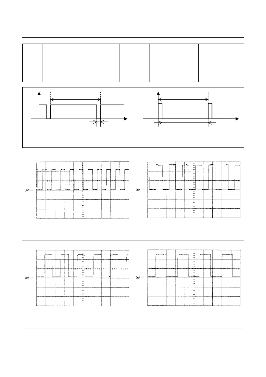
7.14ms 7.14ms
Time Time
0.714ms 6.426ms
V
olt
age
Off duty 10% =Throttle Position 0%
V
olt
age
Off duty 90% =Throttle Position 100%
Engine Speed Sensor Reference Wave Form
Measurement Terminal: A7 (+)
B5 (-)
Measurement Scale: 5V/div
20ms/div
Measurement Condition: At engine speed 1500rpm
Vehicle Speed Sensor Out Reference Wave Form
Measurement Terminal: A10 (+) B5 (-)
Measurement Scale: 5V/div
50ms/div
Measurement Condition: Vehicle speed 20km/h at L
range in 1st gear
Turbine Sensor Reference Wave Form
Measurement Terminal: B3 (+)
B5 (-)
Measurement Scale: 5V/div
500ms/div
Measurement Condition: Vehicle speed 20km/h at L
range in 1st gear
Vehicle Speed Sensor Reference Wave Form
Measurement Terminal: B13 (+) B5 (-)
Measurement Scale: 5V/div
2ms/div
Measurement Condition: Vehicle speed 20km/h at L
range in 1st gear
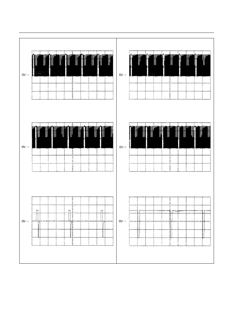
DIAGNOSIS 7A2-161
Low & Reverse Brake Duty Solenoid Reference
Wave Form
Measurement Terminal: B6 (+)
B22 (-)
Measurement Scale: 5V/div
10ms/div
Measurement Condition: P, N range in idle
2-4 Brake Duty Solenoid Reference Wave Form
Measurement Terminal: B7 (+)
B22 (-)
Measurement Scale: 5V/div
20ms/div
Measurement Condition: P, N range in idle
High Clutch Duty Solenoid Reference Wave Form
Measurement Terminal: B8 (+)
B22 (-)
Measurement Scale: 5V/div
20ms/div
Measurement Condition: P, N range in idle
Low Clutch Duty Solenoid Reference Wave Form
Measurement Terminal: B9 (+)
B22 (-)
Measurement Scale: 5V/div
20ms/div
Measurement Condition: D range 4th gear
Lock-up Duty Solenoid Reference Wave Form
Measurement Terminal: B17 (+) B5 (-)
Measurement Scale: 10V/div
5ms/div
Measurement Condition: Unlock-up condition
Lock-up Duty Solenoid Reference Wave Form
Measurement Terminal: B17 (+) B5 (-)
Measurement Scale: 10V/div
5ms/div
Measurement Condition: Lock-up condition
MEMO
Нет комментариевНе стесняйтесь поделиться с нами вашим ценным мнением.
Текст