Isuzu D-Max / Isuzu Rodeo (TFR/TFS). Manual — part 1271
8–4 ELECTRICAL-BODY AND CHASSIS
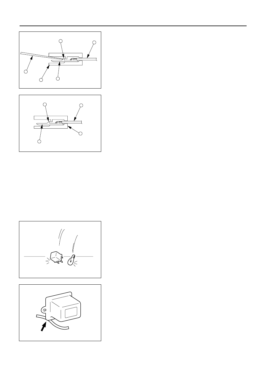
Pin Tang Lock Type
1. Insert a slender shaft 3 into the connector housing
open end 4.
2. Push the tang lock 8 flat (toward the wire side of the
connector).
Pull the wire 6 with pin 7 free from the wire side of
the connector.
6
8
7
4
3
D08RV843
Connector Pin Insertion
1. Check that the tang lock 8 is fully up.
2. Insert the pin 7 from the connector wire side 9.
Push the pin in until the tang lock closes firmly.
3. Gently pull on the wires 6 to make sure that
connector pin is firmly set in place.
6
8
7
9
D08RV842
Fuse Replacement
The replacement fuse must have the same amperage
specification as the original fuse.
Never replace a burn out fuse with a fuse of a different
amperage specification. Doing so can result in an
electrical fire or other serious circuit damage.
Parts Handling
Be careful for parts handling and any part should not be
dropped or thrown, otherwise short circuit or disorder
may result.
D08RV704
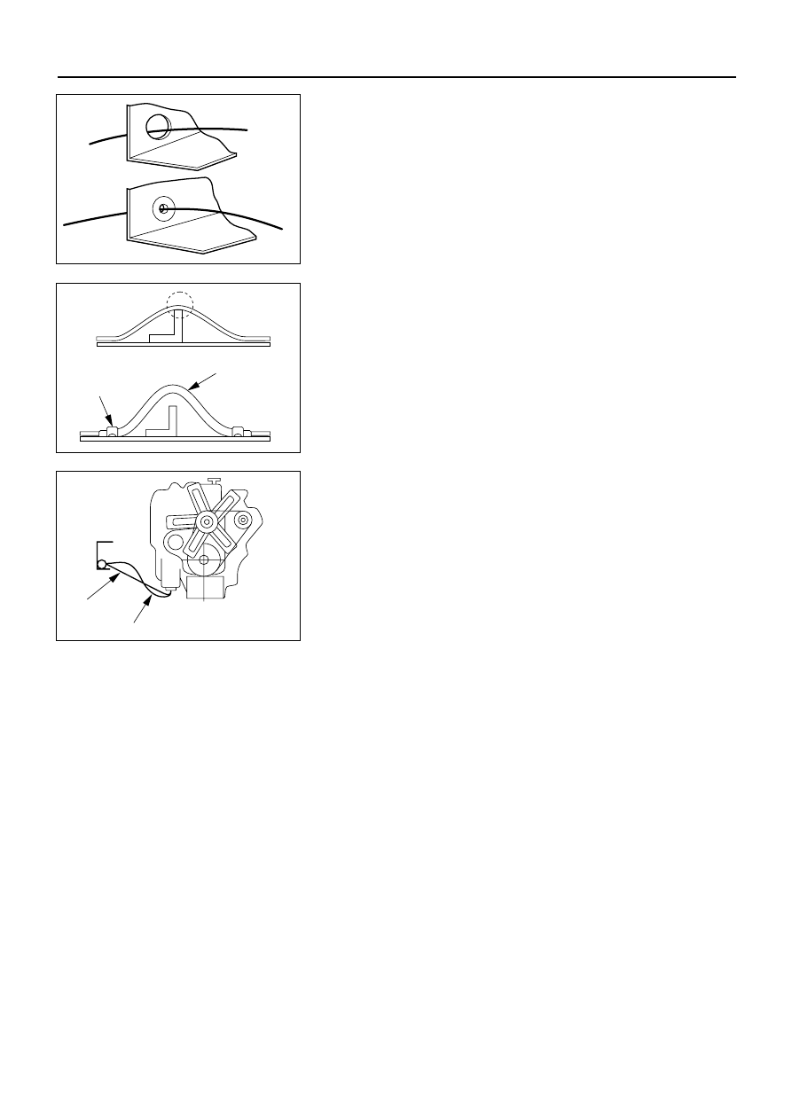
Wiring Harness
1. When assembling the parts, be careful not to bite or
wedge the wiring harness.
2. All electrical connections must be kept clean and
tight.
,
D08RV705
ELECTRICAL-BODY AND CHASSIS 8–5
3. Use a grommet or guard tube to protect the wiring
harness from contacting a sharp edge or surface.
OK
NO
D08RV836
4. Position the wiring harness with enough clearance
from the other parts and guard the wiring harness
with a vinyl tube to avoid direct contact.
,
Vinyl tube
Clip
OK
NO
D08RV837
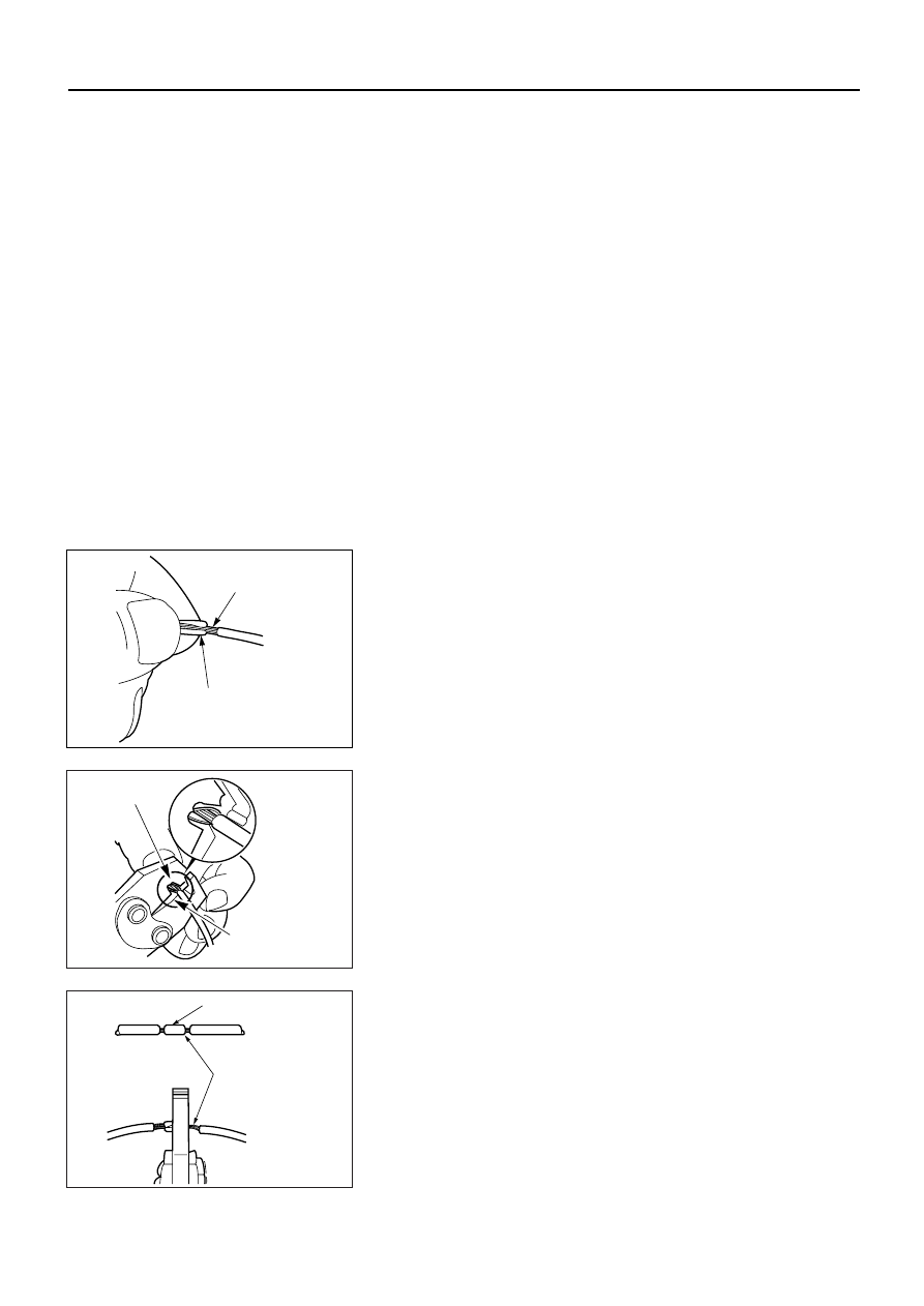
5. The wiring harness between engine and chassis
should be long enough to prevent chafing or damage
due to various vibrations.
NO
OK
D08RV838
8–6 ELECTRICAL-BODY AND CHASSIS
SPLICING WIRE
Open the Harness
If the harness is taped, remove the tape. To avoid wire
insulation damage, use a sewing “seam ripper” (available
from sewing supply stores) to cut open the harness.
If the harness has a black plastic conduit, simply pull out
the desired wire.
Cut the wire
Begin by cutting as little wire off the harness as possible.
You may need the extra length of wire later if you decide
to cut more wire off to change the location of a splice.
You may have to adjust splice locations to make certain
that each splice is at least 1-1/2” (40 mm) away from
other splices, harness branches, or connectors.
Strip the insulation
When replacing a wire, use a wire of the same size as the
original wire. Check the stripped wire for nicks or cut
strands. If the wire is damaged, repeat the procedure on
a new section of wire. The two stripped wire ends should
be equal in length.
Crimp the Wires
Select the proper clip to secure the splice. To determine
the proper clip size for the wire being spliced, follow the
directions included with your clips. Select the correct
anvil on the crimper. (On most crimpers your choice is
limited to either a small or large anvil.) Overlap the two
stripped wire ends and hold them between your thumb
and forefinger.
Then, enter the splice clip under the stripped wires and
hold it in place.
Over lap bare wires
Splice clip
D08RV676
D08RV678
•
Open the crimping tool to its full width and rest one
handle on a firm flat surface.
•
Center the back of the splice clip on the proper anvil
and close the crimping tool to the point where the
back of the splice clip touches the wings of the clip.
•
Make sure that the clip and wires are still in the
correct position. Then, apply steady pressure until
the crimping tool closes.
wing of clip
touching former
Back of clip
centered on anvil
D08RV678
Before crimping the ends of the clip, be sure that:
•
The wires extend beyond the clip in each direction.
•
No strands of wire are cut loose, and
•
No insulation is caught under the clip.
Crimp the splice again, once on each end. Do not let the
crimping tool extend beyond the edge of the clip or you
may damage or nick the wires.
Splice clip
Align tool with
edge of clip to
crimp ends of
splice
D08RV677
ELECTRICAL-BODY AND CHASSIS 8–7
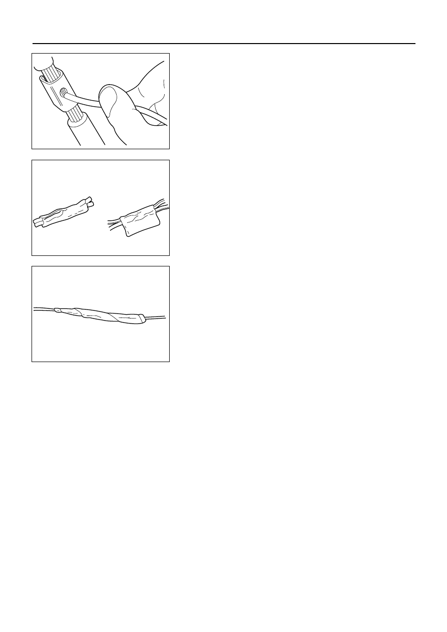
Solder
Apply 60/40 rosin core solder to the opening in the back
of the clip. Follow the manufacturer’s instructions for the
solder equipment you are using.
D08RV679
Tape the Splice
Center and roll the splicing tape. The tape should cover
the entire splice. Roll on enough tape to duplicate the
thickness of the insulation on the existing wires. Do not
flag the tape. Flagged tape may not provide enough
insulation, and the flagged ends will tangle with the other
wires in the harness.
Good (Rolled)
Bad (Flagged)
D08RV680
If the wire does not belong in a conduit or other harness
covering, tape the wire again. Use a winding motion to
cover the first piece of tape.
D08RV681
Нет комментариевНе стесняйтесь поделиться с нами вашим ценным мнением.
Текст