Isuzu D-Max / Isuzu Rodeo (TFR/TFS). Manual — part 1270
ELECTRICAL-BODY AND CHASSIS
Grounding Point . . . . . . . . . . . . . . . . . . . . . . . . . . . . . . . . . . . . . . . . . . . . . . . . . . . . . . . . . . . . 8– 48
Reference Table . . . . . . . . . . . . . . . . . . . . . . . . . . . . . . . . . . . . . . . . . . . . . . . . . . . . . . . . . 8– 48
Location . . . . . . . . . . . . . . . . . . . . . . . . . . . . . . . . . . . . . . . . . . . . . . . . . . . . . . . . . . . . . . . . 8– 52
Main Cable Harness Routing . . . . . . . . . . . . . . . . . . . . . . . . . . . . . . . . . . . . . . . . . . . . . . . . . . . . . 8– 55
System Repair . . . . . . . . . . . . . . . . . . . . . . . . . . . . . . . . . . . . . . . . . . . . . . . . . . . . . . . . . . . . . . . . . 8– 63
Start and Charging . . . . . . . . . . . . . . . . . . . . . . . . . . . . . . . . . . . . . . . . . . . . . . . . . . . . . . . . . . 8– 63
Engine Control Module (ECM) and Fuel Pump. . . . . . . . . . . . . . . . . . . . . . . . . . . . . . . . . . . . 8– 80
Emission Control System. . . . . . . . . . . . . . . . . . . . . . . . . . . . . . . . . . . . . . . . . . . . . . . . . . . . . 8– 96
QOS System . . . . . . . . . . . . . . . . . . . . . . . . . . . . . . . . . . . . . . . . . . . . . . . . . . . . . . . . . . . . . . . 8–102
Lighting . . . . . . . . . . . . . . . . . . . . . . . . . . . . . . . . . . . . . . . . . . . . . . . . . . . . . . . . . . . . . . . . . . . 8–108
Hazard Warning Flasher, Turn Signal Light, Back Up Light,
Horn and Stop Light . . . . . . . . . . . . . . . . . . . . . . . . . . . . . . . . . . . . . . . . . . . . . . . . . . . . . . . . . 8–138
Dome Light, Spot Light and Warning Buzzer. . . . . . . . . . . . . . . . . . . . . . . . . . . . . . . . . . . . . 8–165
Windshield Wiper and Washer . . . . . . . . . . . . . . . . . . . . . . . . . . . . . . . . . . . . . . . . . . . . . . . . 8–178
Overdrive Off (A/T) . . . . . . . . . . . . . . . . . . . . . . . . . . . . . . . . . . . . . . . . . . . . . . . . . . . . . . . . . . 8–194
Transmission Control Module (TCM) . . . . . . . . . . . . . . . . . . . . . . . . . . . . . . . . . . . . . . . . . . . 8–197
Meter, Warning Light and Indicator Light . . . . . . . . . . . . . . . . . . . . . . . . . . . . . . . . . . . . . . . 8–200
Heater and Air Conditioning . . . . . . . . . . . . . . . . . . . . . . . . . . . . . . . . . . . . . . . . . . . . . . . . . . 8–257
Power Door Lock. . . . . . . . . . . . . . . . . . . . . . . . . . . . . . . . . . . . . . . . . . . . . . . . . . . . . . . . . . . . 8–267
Power Window . . . . . . . . . . . . . . . . . . . . . . . . . . . . . . . . . . . . . . . . . . . . . . . . . . . . . . . . . . . . . 8–278
Audio, Clock and Cigarette Lighter . . . . . . . . . . . . . . . . . . . . . . . . . . . . . . . . . . . . . . . . . . . . . 8–298
Power Door Mirror . . . . . . . . . . . . . . . . . . . . . . . . . . . . . . . . . . . . . . . . . . . . . . . . . . . . . . . . . . 8–306
Rear Defogger . . . . . . . . . . . . . . . . . . . . . . . . . . . . . . . . . . . . . . . . . . . . . . . . . . . . . . . . . . . . . . 8–318
Radiator Level Control Warning System . . . . . . . . . . . . . . . . . . . . . . . . . . . . . . . . . . . . . . . . 8–327
Connector List . . . . . . . . . . . . . . . . . . . . . . . . . . . . . . . . . . . . . . . . . . . . . . . . . . . . . . . . . . . . . . . . . 8–330
ELECTRICAL-BODY AND CHASSIS 8–1
GENERAL INFORMATION
The body and chassis electrical system operates on a twelve volt power supply with negative ground
polarity.
The main harness consists of the engine harness, the instrument harness, the body harness, and the
chassis harness.
The harnesses use a split corrugated tube to protect the wires from the elements.
Wire size is determined by current flow, circuit length, and voltage drop.
All wires have color-coded insulation.
Wire color-codes are shown in the circuit diagrams. This makes it easier to trace circuits and to make the
proper connections.
Each circuit consists of the following:
1. Power source - The battery and the alternator
2. Wires - To carry electrical current through the circuit
3. Fuses - To protect the circuit against current overload
4. Relays - To protect voltage drop between the battery and the circuit parts and to protect the switch
points against burning
5. Switches - To open and close the circuit
6. Load - Any device, such as a light or a motor, which converts the electrical current into useful work
7. Ground - To allow the current to flow back to the power source
8–2 ELECTRICAL-BODY AND CHASSIS
NOTES FOR WORKING ON ELECTRICAL ITEMS
BATTERY CABLE
Disconnecting the Battery Cable
1. All switches should be “OFF” position.
2. Disconnect the battery ground cable.
3. Disconnect the battery positive cable.
CAUTION:
It is important that the battery ground cable be
disconnected first.
Disconnecting the battery positive cable first can result in
a short circuit.
Connecting the Battery Cable
Follow the disconnecting procedure in the reverse order
to connect the battery cables.
CAUTION:
Clean the battery terminal and apply light coat of grease
to prevent terminal corrosion.
Positive cable
Ground cable
D08RV758
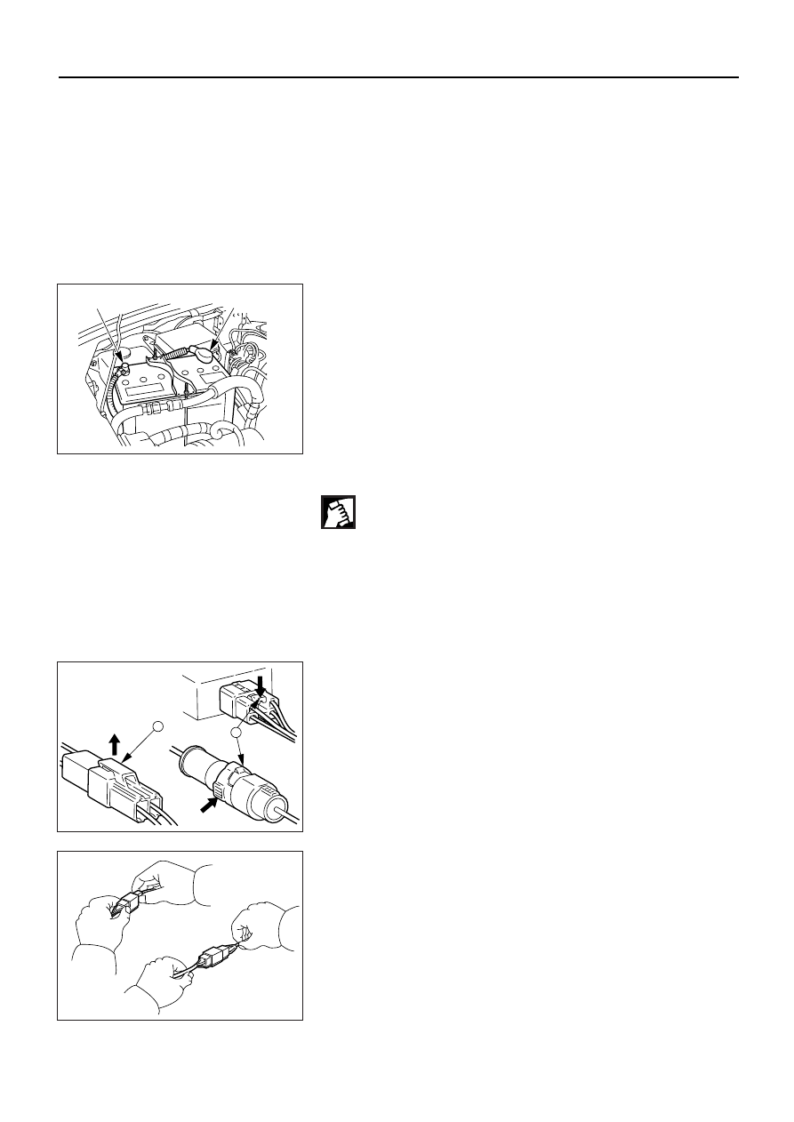
CONNECTOR HANDLING
Disconnecting the Connectors
Some connectors have a tang lock to hold the connectors
together during vehicle operation.
Some tang locks are released by pulling them towards
you 1.
Other tang locks are released by pressing them forward
2.
Determine which type of tang lock is on the connector
being handled.
1
2
D08RV879
Firmly grasp both sides (male and female) of the
connector.
Release the tang lock and carefully pull the two halves of
the connector apart.
Never pull on the wires to separate the connectors. This
will result in wire breakage.
OK
NO
D08RV839
ELECTRICAL-BODY AND CHASSIS 8–3
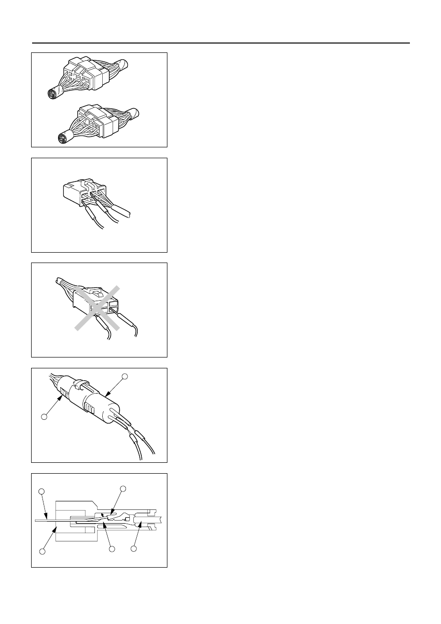
Connecting the Connectors
Firmly grasp both sides (male and female) of the
connector.
Be sure that the connector pins and pin holes match.
Be sure that both sides of the connector are aligned with
each other.
Firmly but carefully push the two sides of the connector
together until a distinct click is heard.
BAD
GOOD
D08RV672
Connector Inspection
Use a circuit tester to check the connector for continuity.
Insert the test probes from the connector wire side.
D08RV673
CAUTION
Never insert the circuit tester test probes into the
connector open side to test the continuity.
Broken or open connector terminals will result.
D08RV674
Waterproof Connector Inspection
It is not possible to insert the test probes into the
connector wire side of a waterproof connector.
Use one side of a connector 1 with its wires cut to make
the test.
Connect the test connector to the connector 2 to be
tested.
Connect the test probes to the cut wires to check the
connector continuity.
1
2
D08RV841
Connector Pin Removal
Connector Housing Tang Lock Type
1. Insert a slender shaft 3 into the connector housing
open end 4.
2. Push the tang lock 5 up (in the direction of the arrow
in the illustration).
Pull the wire 6 with pin 7 free from the wire side of
the connector.
,
,
7
4
3
5
6
D08RV844
Нет комментариевНе стесняйтесь поделиться с нами вашим ценным мнением.
Текст