Isuzu D-Max / Isuzu Rodeo (TFR/TFS). Manual — part 1765

DIAGNOSIS 7A2-111
Step
Action
Yes
No
6
Inspect the output voltage and throttle opening signal of the
throttle position sensor using a Tech 2 or circuit tester.
Is a voltage value in proportion to the throttle opening output?
TPS
TCM
A16
C56
(28)
C94
(16)
RED/WHT
C56
(49)
(38)
(57)
(69)
ECM
A47 (GND)
A35 (Output)
A26
A55 (+5V)
A69 (Idle SW)
Go to Step 7
Repair the defect or
replace.
7
Check of power supply to and earth of TCM.
Are the power supply and earth proper?
TCM
A1 (+B)
B5
B15
H23
(15)
C95
(5)
(15)
BLK/YEL
BLK
BLK
Battery
C94
(1)
BLK
Go to Step 8
Check the power
source harness and
earth harness (bolt
tightening to the
body).
8
Is the stall revolution correct in D, 3, 2 and L range? Refer the
STALL TEST section in this manual.
Go to Step 9
Repair the defect or
replace.
9
Is the line pressure correct? Refer the LINE PRESSURE TEST
section in this manual.
Trouble in the AT
assembly or control
valve.
Repair the defect or
replace.
7A2-112 DIAGNOSIS
No. C9: Barking Feel When Gear is Shifted Up to 1st to 2nd
No. C10: Barking Feel When Gear is Shifted Up to 2nd to 3rd
No. C11: Barking Feel When Gear is Shifted Up to 3rd to 4th
Description:
•
Brake feeling appears when the accelerator pedal is stepped on for acceleration and the gear is shifted up.
Diagnosis Hints:
•
Possibility of slip of clutch is supposed. If slip of clutch has occurred, a DTC of "Gear ratio error" is stored.
Possible Cause:
•
Slip
of
clutch.
If slip of clutch is caused, a DTC (gear ratio error) is stored.
•
Dropped line pressure.
•
Trouble in control valve body (faulty operation, sticking, clogged oil passage).
DIAGNOSIS 7A2-113
Step
Action
Yes
No
1
Gear ratio trouble diagnosis.
Travel in the following sequence for about 7 seconds or more in
each range: Start in the L range (1st) to 2 range (2nd) to 3 range
(3rd) to D range (4th) (to detect the gear ratio trouble exactly, this
process should be carried out)
Go to Step 2
Go to Step 2
2
Are any DTCs stored?
Go to DTC Chart
Go to Step 3
3
Are the quantity, contamination and smell normal?
If the ATF level is
low, replenish up to
the specified level.
Go to Step 4
If ATF is extremely
black and
contaminated and
smells burnt, slip of
the clutch is
supposed.
Overhaul the AT
unit.
4
Are the engine speed and other engine system correct?
Go to Step 5
Repair the defect or
replace.
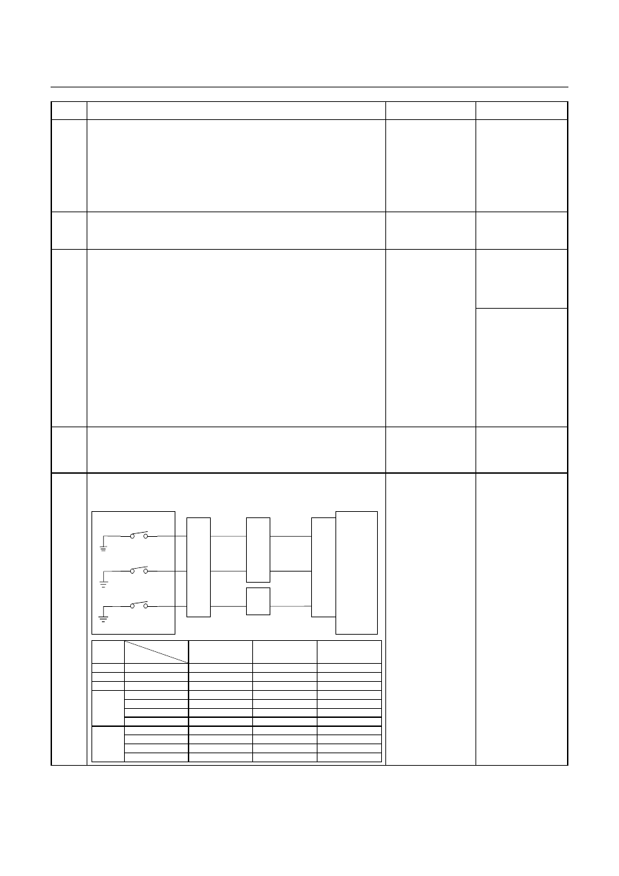
5
Inspection of electrical or mechanical fault
Is the signal from each pressure switch changed synchronously?
Control Valve
TCM
B1
B12
B20
RED/YEL
WHT/BLK
2-4 Brake Pressure SW
Terminal
Assembly
YEL
E54
(7)
(12)
(1)
H23
(12)
(10)
C95
(1)
(12)
(20)
RED/YEL
YEL
WHT/BLK
L&R Brake Pressure SW
High Clutch Pressure SW
H22
(8)
Range
TCM terminal
Gear
B20
(High clutch
pressure SW)
B1
(2-4 brake pressure
SW)
B12 (Low & reverse
brake pressure SW)
P
-
More than 10V
More than 10V
More than 10V
R
Reverse
More than 10V
More than 10V
-
N
-
More than 10V
More than 10V
More than 10V
D, 3, 2
1st
More than 10V
More than 10V
More than 10V
2nd
More than 10V
-
More than 10V
3rd
-
More than 10V
More than 10V
4th
-
-
More than 10V
L
1st
More than 10V
More than 10V
-
2nd
More than 10V
-
More than 10V
3rd
-
More than 10V
More than 10V
4th
-
-
More than 10V
Go to Step 6
Repair the defect or
replace.
7A2-114 DIAGNOSIS
Step
Action
Yes
No
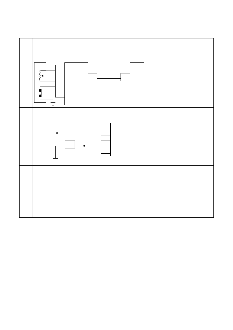
6
Inspect the output voltage and throttle opening signal of the
throttle position sensor using a Tech 2 or circuit tester.
Is a voltage value in proportion to the throttle opening output?
TPS
TCM
A16
C56
(28)
C94
(16)
RED/WHT
C56
(49)
(38)
(57)
(69)
ECM
A47 (GND)
A35 (Output)
A26
A55 (+5V)
A69 (Idle SW)
Go to Step 7
Repair the defect or
replace.
8
Check of power supply to and earth of TCM.
Are the power supply and earth proper?
TCM
A1 (+B)
B5
B15
H23
(15)
C95
(5)
(15)
BLK/YEL
BLK
BLK
Battery
C94
(1)
BLK
Go to Step 9
Check the power
source harness and
earth harness (bolt
tightening to the
body).
9
Is the stall revolution correct in D, 3, 2 and L range? Refer the
STALL TEST section in this manual.
Go to Step 10
Repair the defect or
replace.
10
Is the line pressure correct? Refer the LINE PRESSURE TEST
section in this manual.
Trouble in the AT
assembly or control
valve.
Repair the defect or
replace.
Нет комментариевНе стесняйтесь поделиться с нами вашим ценным мнением.
Текст