Isuzu D-Max / Isuzu Rodeo (TFR/TFS). Manual — part 973

4C1-62 FRONT WHEEL DRIVE
9. Inner Cam
(1) Before installation, shift the transfer lever to “2H” position.
(2) Clean the flange surface of the hub, the thread holes, the
surface of the lock washer and the spline portion of the axle
shaft.
(3) Install the inner cam by aligning the key way of the inner
cam with the groove of the knuckle.
Hit the inner cam lightly with plastic hammer or equivalent
and make sure the inner cam is in contact with the lock
washer.
If it is difficult to install the inner cam, use the tool (installer)
and a plastic hammer or the equivalent.
Install the special tool.
Use the plastic hammer to lightly tap around the special tool “A”
surface as shown in the illustration.
Installer : 58840-2137-0 (J-38194)
Note: Do not strike the inner cam gear teeth with the plastic
hammer.
Shim Selection
(1) Lower vehicle from hoist.
(2) Support lower link with floor jack, placing axle in normal
horizontal position.

FRONT WHEEL DRIVE 4C1-63
(3) Install special tool 5-8840-2126-0 to axle shaft by 5-8840-
2125-0 until it comes into contact with the lock washer.
(4) Using feeler gauge, measure clearance “t” between the
special tool and the snap ring groove of the axle shaft.
(5) If clearance “t” is larger than snap ring groove, shims must
be installed select shims so that clearance “t” is 0 to 0.1 mm
(0 to 0.0039 in).
Thickness shims; 0.2, 0.3, 0.5, 1.0 mm
(6) Remove special tool 5-8840-2126-0, leaving the inner cam
in position.
10.Drive Clutch Assembly
Apply multipurpose grease or hub bearing grease to the
following portions.
(1) Axle shaft splines
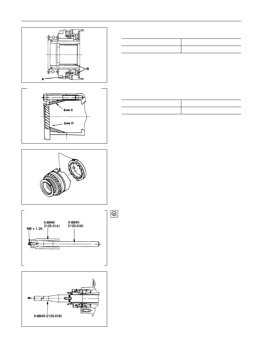
4C1-64 FRONT WHEEL DRIVE
•
“A” groove and “B” portion
g(oz)
“A” Groove
7 (0.25)
“B” portion
3 (0.11)
•
“C” circumference and “D” portion
g(oz)
“C” circumference
8 (0.29)
“D” portion
4 (0.15)
(2) Align the cut part of the drive clutch assembly with the
protudent part of inner cam.
(3) Engage the cam teeth of the drive clutch assembly to that of
the inner cam by turning the axle shaft.
11.Snap Ring and Shims
(1) Install shims (selected above) to axle by hand.
Note :
Always use a new snap ring.
(2) Install special tool 5-8840-2125-0 (B) to axle.
(3) Install snap ring to tool.
(4) Install tool driver 5-8840-2125-0 (A).
(5) Pull out the axle shaft fully by pulling the tool 5-8840-2125-0
(B) and install snap ring to axle by pushing on tool driver 5-
8840-2125-0 (A).
(6) Remove tool from axle.
Snap ring installer : 5-8840-2125-0
(J-36835)
FRONT WHEEL DRIVE 4C1-65
Caution
After installation of the shims and the snap ring, check the
fitting condition of the snap ring.
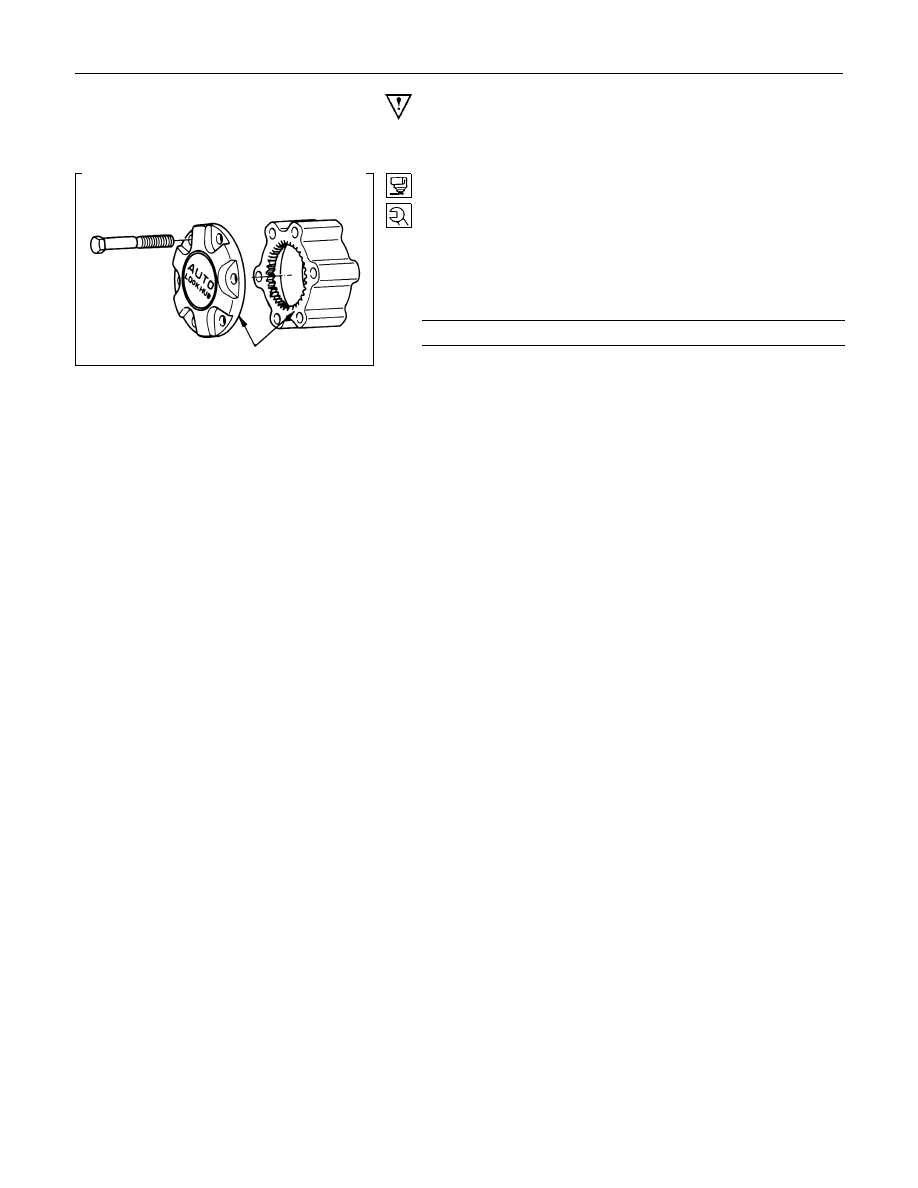
12.Housing Assembly
(1) Apply Loctite 515 or the equivalent to the flange surface of
the housing assembly.
(2) Make sure that the housing assembly turns smoothly.
If it turns smoothly, the spacer selected above is correct.
(3) Bolt tightening torque :
Torque
N
⋅
m (kgf
⋅
m/lb
⋅
ft)
58.9
±
5 (6
±
0.5/43.4
±
3.6)
Нет комментариевНе стесняйтесь поделиться с нами вашим ценным мнением.
Текст