Isuzu D-Max / Isuzu Rodeo (TFR/TFS). Manual — part 971
4C1-54 FRONT WHEEL DRIVE
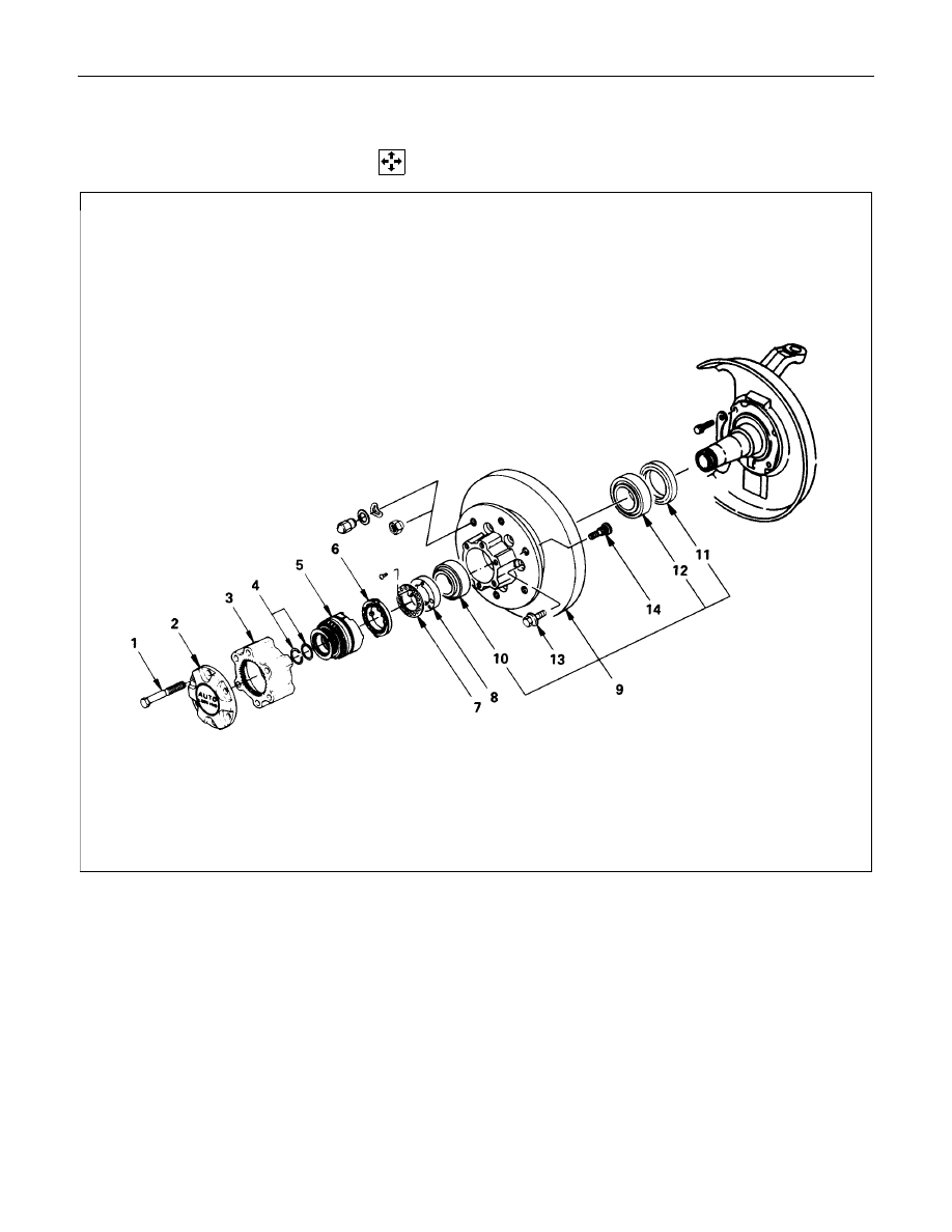
FRONT HUB AND DISC (Automatic Locking Hub)
DISASSEMBLY
Disassembly Steps
▲
1. Bolt
2. Hub cap
3. Housing assembly
4. Snap ring and shim
5. Drive clutch assembly
6. Inner cam
7. Lock washer
▲
8. Hub nut
▲
9. Hub and disc assembly
▲
10. Outer bearing and outer race
11. Oil seal
▲
12. Inner bearing and outer race
▲
13. Bolt
▲
14. Wheel pin
FRONT WHEEL DRIVE 4C1-55
Important Operations
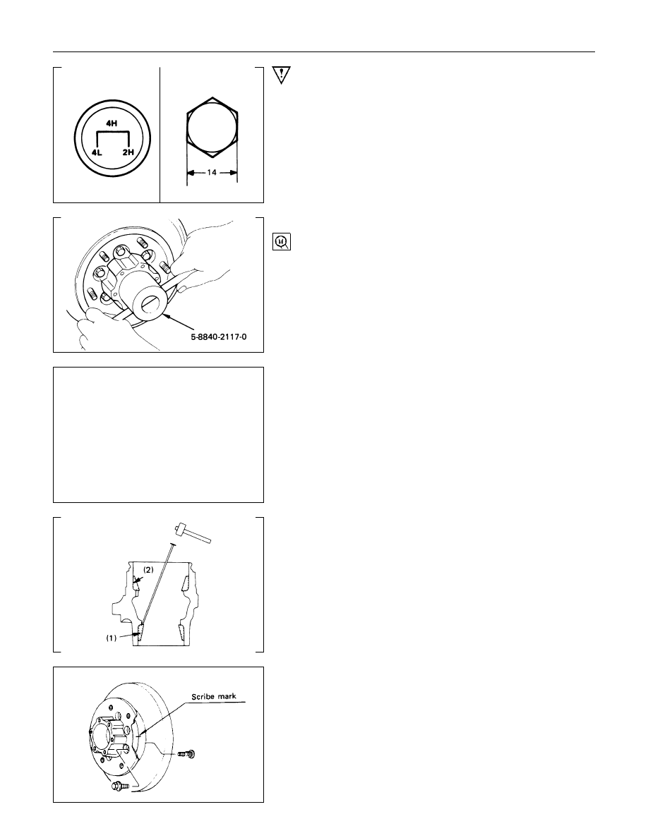
1. Bolt
Shift the transfer lever to the “2H” position and move the
vehicle forward and rearward about one meter.
Remove the 14 mm hex bolts.
8. Hub Nut
Wrench : 5-8840-2117-0
(J-36827)
Refer to Section 5 “Brake” for disc brake
caliper removal procedure
9. Hub and Disc Assembly
Before disassembly, remove the disc brake caliper assembly
and hang it on the frame with wires.
10.Outer Bearing and Outer Race
12.Inner Bearing and Outer Race
(1) Remove the outer bearing from the hub with fingers. The
inner bearing will remain in the hub and may be removed
after prying out the inner bearing lip seal assembly.
(2) Remove the outer race by driving out the race from the hub
with a brass drift inserted behind the race in the notches in
the hubs.
If necessary, replace the wheel pin in the following manner.
13.Bolt
(1) Apply a scribe mark to disc to hub.
(2) Clamp the hub and disc assembly in a vise using protective
pads and remove the 6 disc to hub retaining bolts.

4C1-56 FRONT WHEEL DRIVE
14.Wheel Pin
Place pins hub on a suitable work surface and remove the
wheel studs, as required, using a hammer.

FRONT WHEEL DRIVE 4C1-57
INSPECTION AND REPAIR
Make necessary correction or parts replacement if wear, damage or any other abnormal conditions are found
through inspection.
For inspection and servicing of disc caliper, and relative parts, refer to Section 5 “Service Brakes”.
•
Hub
•
Hub bearing, oil seal
•
Knuckle spindle
•
Disc
•
Caliper
•
Automatic locking hubs
Visual Check
Check the following parts for wear, damage or other abnormal
conditions.
Inside Diameter of Housing
mm(in)
Standard
Limit
65.04 (2.61)
65.24 (2.568)
Inspect flange surface A and B for excessive wear.
Drive Clutch Section Dimensions “L”
mm(in)
Standard
Limit
8.2 (0.323)
7.8 (0.37)
Holdout Ring Axial Play of the Drive
Clutch Assembly
mm(in)
Standard
Limit
0.3 (0.012) or less
0.4 (0.016)
Нет комментариевНе стесняйтесь поделиться с нами вашим ценным мнением.
Текст