Isuzu D-Max / Isuzu Rodeo (TFR/TFS). Manual — part 967
4C1-38 FRONT WHEEL DRIVE
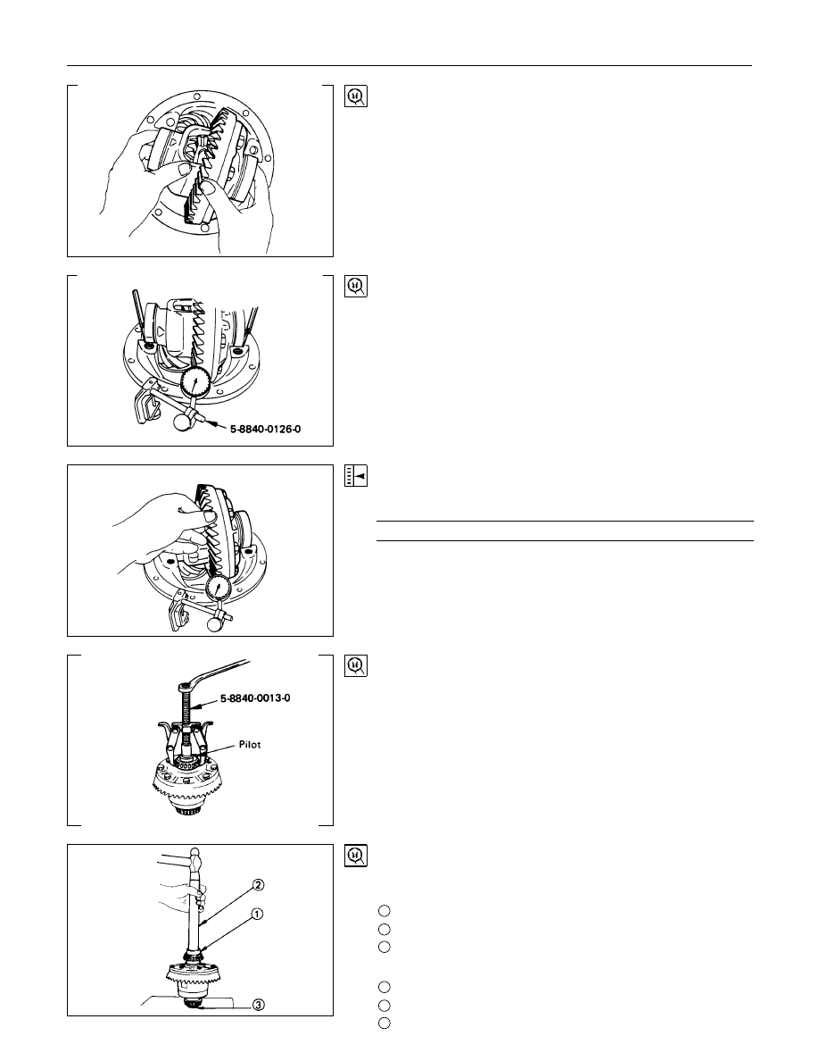
(2) Insert the differential cage assembly with bearing outer
races into the side bearing bores of the carrier.
(3) Using two sets of feeler gauges, insert a feeler stock of
sufficient thickness between each bearing outer race and
the carrier to remove all end plat. Make certain the feeler
stock is pushed to the bottom of the bearing bores.
Mount the dial indicator on the carrier so that the indicator
stem is at right angles to a tooth on the ring gear.
Dial indicator : 5884-0126-0
(J-8001)
(4) Adjust feeler gauge thickness from side to side until ring
gear backlash is in the specified range.
Backlash
mm(in)
0.13 - 0.18 (0.005 - 0.007)
With zero end play and correct backlash established,
remove the feeler gauge packs, determine the thickness of
the shims required and add 0.05 mm (0.002 in) to each
shim pack to provide side bearing preload. Always use new
shims.
(5) Remove side bearing
Remover : 5-8840-0013-0
(J-22888)
Pilot
: 5-8521-0019-0 (167 mm)
9-8521-1743-0 (194 mm)
(J-8107-2)
14.Side Bearing
Install the side bearings together with the selected shims.
For 167 mm
1
Installer
: 5-8840-0138-0 (J-29036)
2
Drive handle : 5-8840-0007-0 (J-8092)
3
Pilot : 5-8521-0019-0
For 194 mm
1
Installer
: 9-8521-1164-0 (J-24244)
2
Drive handle : 5-8840-0007-0 (J-8092)
3
Pilot
: 9-8521-1743-0 (J-8107-2)
FRONT WHEEL DRIVE 4C1-39
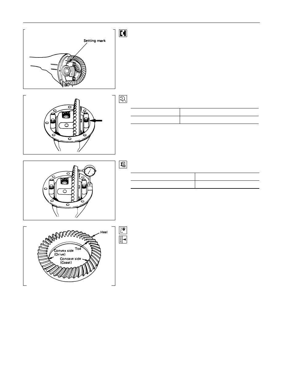
17.Bearing Cap
Align the setting marks applied at disassembly.
18.Bolt
Bolt Torque
N
⋅
m (kgf
⋅
m/lb
⋅
ft)
167 mm
68.7
±
9.8 (7.0
±
1.0/50.6
±
7.2)
194 mm
98.1
±
9.8 (10.0
±
1.0/72.3
±
7.2)
Measure the amount of run-out of the ring gear at its rear face.
mm(in)
Standard
Limit
0.02 (0.001)
0.05 (0.002)
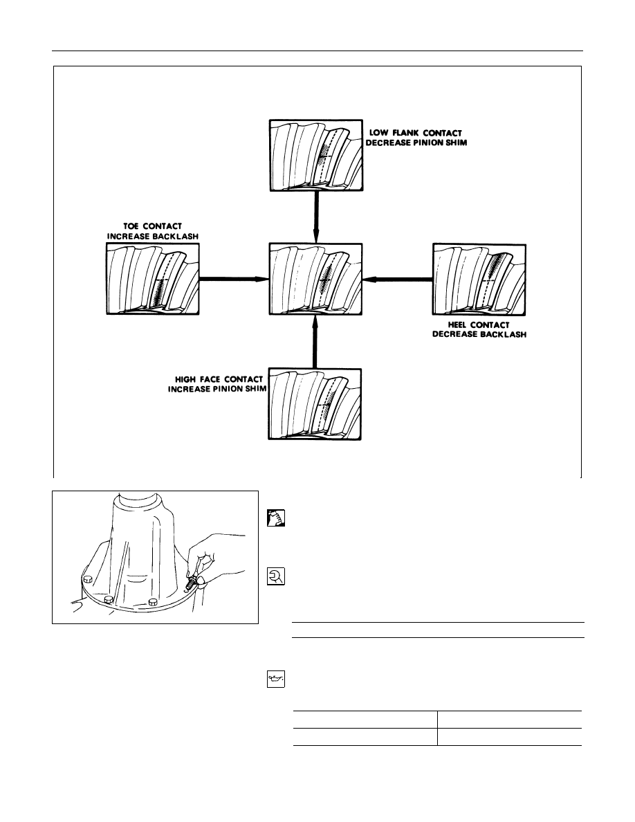
Gear Tooth Contact Pattern Check and Adjustment
Apply a thin coat of prussian blue or equivalent to the faces of
the 7 - 8 teeth of the ring gear. Check the impression of
contact on the ring gear teeth and make necessary adjustment
as described below if the contact is abnormal.
4C1-40 FRONT WHEEL DRIVE
20.Differential Assembly
(1) Clean the faces of the front axle case and differential
carrier.
Apply the recommended liquid gasket or its equivalent to
the sealing side of the axle case and the carrier.
(2) Attach the differential case and the carrier assembly to the
front axle case and tighten the nuts and bolts. The axle
case bolt is used for drainage.
Torque
N
⋅
m (kgf
⋅
m/lb
⋅
ft)
25.5
±
5 (2.6
±
0.5/18.8
±
3.6)
(3) Install the axle shaft assemblies as instructed earlier in this
section under “Axle Shaft Replacement”.
(4) Fill the axle case with hypoid gear lubricant, to just below
the filler hole.
Lubricant capacity
liter (US/UK gal)
167 mm
1.0 (0.26/0.22)
194 mm
1.4 (0.37/0.31)
FRONT WHEEL DRIVE 4C1-41
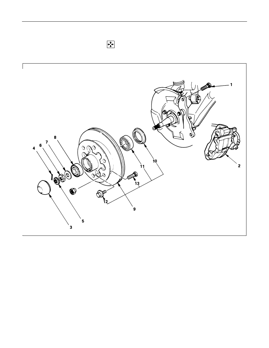
FRONT HUB AND DISC (4
×
2 model)
DISASSEMBLY
Refer to SECTION 3E “WHEEL AND TIRE” for wheel removal procedure.
Disassembly Steps
1. Bolt
▲
2. Brake caliper
▲
3. Hub cap
4. Split pin
5. Nut retainer
6. Hub nut
7. Lock washer
8. Outer bearing
▲
9. Hub and disc assembly
10. Oil seal
11. Inner bearing and outer race
▲
12. Bolt
▲
13. Wheel pin
Нет комментариевНе стесняйтесь поделиться с нами вашим ценным мнением.
Текст