Isuzu D-Max / Isuzu Rodeo (TFR/TFS). Manual — part 1768

DIAGNOSIS 7A2-123
Step
Action
Yes
No
4
Inspection of inhibitor switch using a Tech 2 or circuit tester.
When the select lever is operated, is the data display in the Tech
2 correct or voltage at each range correct?
Inhibitor SW
TCM
A2 (P)
A17 (3)
B2 (2)
B10 (N)
B11 (D)
B19 (R)
B21 (L)
C95
(2)
(10)
(11)
(19)
(21)
YEL/VIO
RED/BLK
BLU
BLK/GRN
Starter Relay
C94
(2)
(3)
B
H22
(1)
(6)
(4)
(7)
(5)
(2)
P
2
R
N
D
3
L
Start SW
PNK/BLU
E51
(2)
(4)
(8)
(5)
(1)
(9)
(6)
(3)
(10)
(7)
(38)
(15)
(3)
(37)
H4
PNK/BLK
RED/YEL
YEL/VIO
BLK/GRN
PNK/BLK
RED/BLK
BLU
RED/YEL
PNK/BLU
BLK/WHT
BLK
BLK
BLK/WHT
Key Switch
WHT
WHT
Immobiliser Control Unit
TCM terminal
Range
A2
B19
B10
B11
B17
B2
B21
P
Battery
voltage
-
-
-
-
-
-
R
-
Battery
voltage
-
-
-
-
-
N
-
-
Battery
voltage
-
-
-
-
D
-
-
-
Battery
voltage
-
-
-
3
-
-
-
-
Battery
voltage
-
-
2
-
-
-
-
-
Battery
voltage
-
L
-
-
-
-
-
-
Battery
voltage
Go to Step 5
Adjust the inhibitor
switch.
5
Inspect the output voltage and throttle opening signal of the
throttle position sensor using a Tech 2 or circuit tester.
Is a voltage value in proportion to the throttle opening output?
TPS
TCM
A16
C56
(28)
C94
(16)
RED/WHT
C56
(49)
(38)
(57)
(69)
ECM
A47 (GND)
A35 (Output)
A26
A55 (+5V)
A69 (Idle SW)
Go to Step 6
Repair the defect or
replace.

7A2-124 DIAGNOSIS
Step
Action
Yes
No
6
Check of power supply to and earth of TCM.
Are the power supply and earth proper?
TCM
A1 (+B)
B5
B15
H23
(15)
C95
(5)
(15)
BLK/YEL
BLK
BLK
Battery
C94
(1)
BLK
Go to Step 7
Check the power
source harness and
earth harness (bolt
tightening to the
body).
7
Inspection of speed sensor and turbine sensor
Have the speed sensor and turbine sensor failed at the same
time? (No DTC is stored at the time of trouble)
Repair the defect or
replace.
Go to Step 8
8
Is the stall revolution correct in D, 3, 2 and L range? Refer the
STALL TEST section in this manual.
Go to Step 9
Repair the defect or
replace.
9
Is the line pressure correct? Refer the LINE PRESSURE TEST
section in this manual.
Trouble in the AT
assembly or control
valve.
Repair the defect or
replace.

DIAGNOSIS 7A2-125
No. E2: Only 4th gear (O/D) is Not Selectable
Description:
•
Gear is not shifted up from 3rd to 4th though the vehicle is accelerated.
Possible Cause:
•
Disordered select cable.
•
Disordered inhibitor switch.
•
ATF thermo sensor detects low oil temperature (4th gear is prohibited temperature less than 10
°
C.).
•
Clogged oil passage of low clutch duty solenoid.
•
Trouble in control valve body (faulty operation, sticking, clogged oil passage).
Step
Action
Yes
No
1
Dislocation or disordered of select lever.
Does the vehicle move when the brake is released in a position
other than the P range and the vehicle is pushed?
Go to Step 2
Adjust the select
cable.
2
Gear ratio trouble diagnosis.
Travel in the following sequence for about 7 seconds or more in
each range: Start in the L range (1st) to 2 range (2nd) to 3 range
(3rd) to D range (4th) (to detect the gear ratio trouble exactly, this
process should be carried out)
Go to Step 3
Go to Step 3
3
Are any DTCs stored?
Go to DTC Chart
Go to Step 4
4
Are the quantity, contamination and smell normal?
If the ATF level is
low, replenish up to
the specified level.
Go to Step 5
If ATF is extremely
black and
contaminated and
smells burnt, slip of
the clutch is
supposed.
Overhaul the AT
unit.
7A2-126 DIAGNOSIS
Step
Action
Yes
No
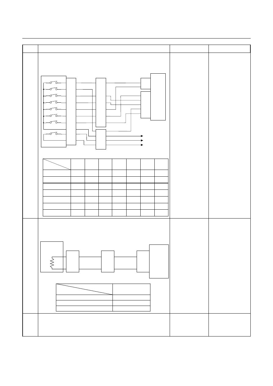
5
Inspection of inhibitor switch using a Tech 2 or circuit tester.
When the select lever is operated, is the data display in the Tech
2 correct or voltage at each range correct?
Inhibitor SW
TCM
A2 (P)
A17 (3)
B2 (2)
B10 (N)
B11 (D)
B19 (R)
B21 (L)
C95
(2)
(10)
(11)
(19)
(21)
YEL/VIO
RED/BLK
BLU
BLK/GRN
Starter Relay
C94
(2)
(3)
B
H22
(1)
(6)
(4)
(7)
(5)
(2)
P
2
R
N
D
3
L
Start SW
PNK/BLU
E51
(2)
(4)
(8)
(5)
(1)
(9)
(6)
(3)
(10)
(7)
(38)
(15)
(3)
(37)
H4
PNK/BLK
RED/YEL
YEL/VIO
BLK/GRN
PNK/BLK
RED/BLK
BLU
RED/YEL
PNK/BLU
BLK/WHT
BLK
BLK
BLK/WHT
Key Switch
WHT
WHT
Immobiliser Control Unit
TCM terminal
Range
A2
B19
B10
B11
B17
B2
B21
P
Battery
voltage
-
-
-
-
-
-
R
-
Battery
voltage
-
-
-
-
-
N
-
-
Battery
voltage
-
-
-
-
D
-
-
-
Battery
voltage
-
-
-
3
-
-
-
-
Battery
voltage
-
-
2
-
-
-
-
-
Battery
voltage
-
L
-
-
-
-
-
-
Battery
voltage
Go to Step 6
Adjust the inhibitor
switch.
6
Inspection of ATF oil thermo sensor.
Is the ATF oil temperature sensor terminal voltage correct?
After running using the Tech 2 data display function, is the ATF
temperature higher than 10
°
C?
ATF
Temp.
Sensor
TCM
B4 (+)
B14 (-)
H23
(8)
(3)
C95
(4)
(14)
BLU
Terminal
Assembly
BLU/BLK
E54
(2)
(8)
BLU
BLU/BLK
T C M te r m in a l
Te m p e r a tu r e
B 4
( O u tp u t v o lta g e )
2 0
1 . 5 5
4 0
1 . 0 8
6 0
0 .7
Go to Step 7
Repair the defect or
replace.
7
Is the stall revolution correct in D, 3, 2 and L range? Refer the
STALL TEST section in this manual.
Go to Step 8
Repair the defect or
replace.
Нет комментариевНе стесняйтесь поделиться с нами вашим ценным мнением.
Текст