Isuzu D-Max / Isuzu Rodeo (TFR/TFS). Manual — part 1767

DIAGNOSIS 7A2-119
Step
Action
Yes
No
6
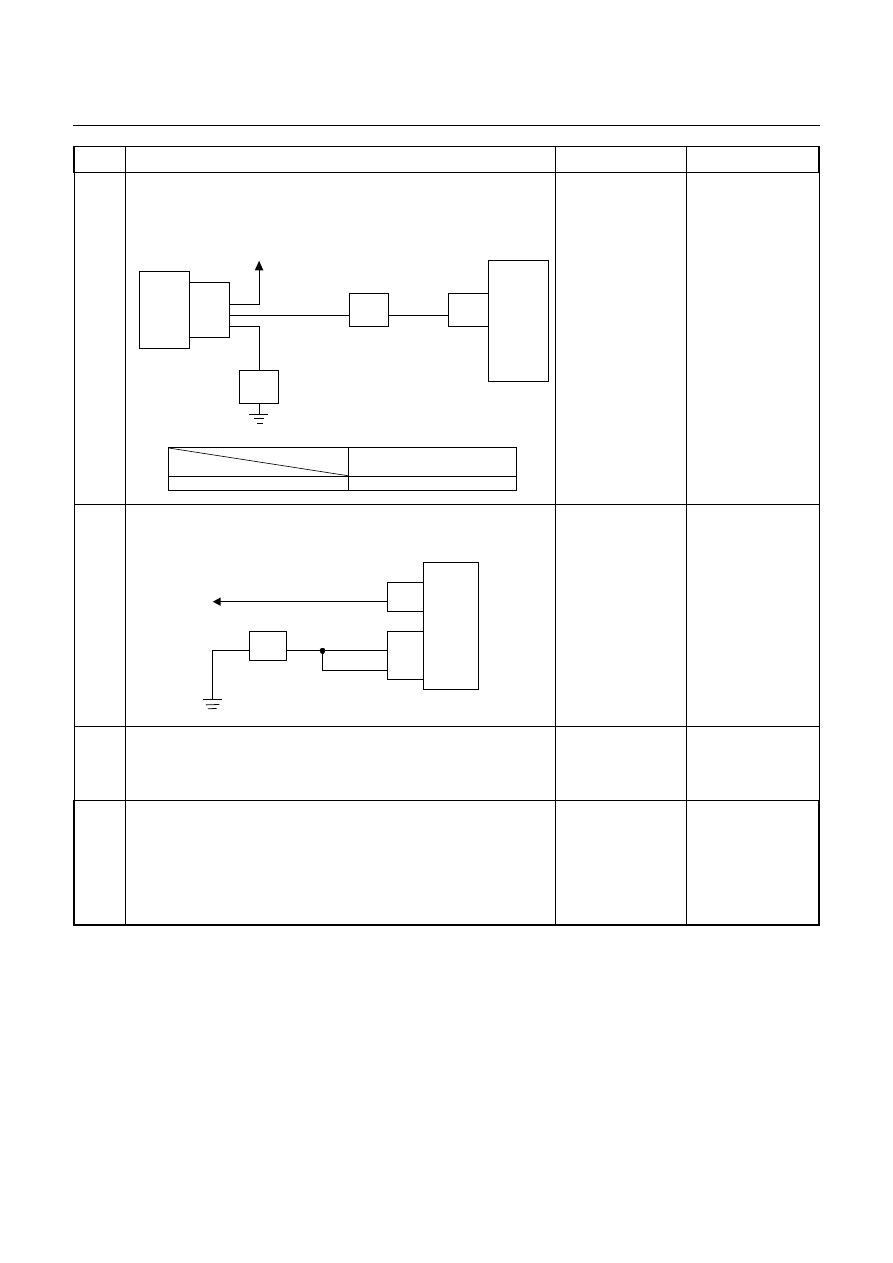
Inspection of inhibitor switch using a Tech 2 or circuit tester.
Inspect the output voltage and throttle opening signal of the
throttle position sensor using a Tech 2 or circuit tester.
Inhibitor SW
TCM
A2 (P)
A17 (3)
B2 (2)
B10 (N)
B11 (D)
B19 (R)
B21 (L)
C95
(2)
(10)
(11)
(19)
(21)
YEL/VIO
RED/BLK
BLU
BLK/GRN
Starter Relay
C94
(2)
(3)
B
H22
(1)
(6)
(4)
(7)
(5)
(2)
P
2
R
N
D
3
L
Start SW
PNK/BLU
E51
(2)
(4)
(8)
(5)
(1)
(9)
(6)
(3)
(10)
(7)
(38)
(15)
(3)
(37)
H4
PNK/BLK
RED/YEL
YEL/VIO
BLK/GRN
PNK/BLK
RED/BLK
BLU
RED/YEL
PNK/BLU
BLK/WHT
BLK
BLK
BLK/WHT
Key Switch
WHT
WHT
Immobiliser Control Unit
TCM terminal
Range
A2
B19
B10
B11
B17
B2
B21
P
Battery
voltage
-
-
-
-
-
-
R
-
Battery
voltage
-
-
-
-
-
N
-
-
Battery
voltage
-
-
-
-
D
-
-
-
Battery
voltage
-
-
-
3
-
-
-
-
Battery
voltage
-
-
2
-
-
-
-
-
Battery
voltage
-
L
-
-
-
-
-
-
Battery
voltage
Go to Step 7
Adjust the inhibitor
switch.
7
Is a voltage value in proportion to the throttle opening output?
TPS
TCM
A16
C56
(28)
C94
(16)
RED/WHT
C56
(49)
(38)
(57)
(69)
ECM
A47 (GND)
A35 (Output)
A26
A55 (+5V)
A69 (Idle SW)
Go to Step 8
Repair the defect or
replace.
7A2-120 DIAGNOSIS
Step
Action
Yes
No
8
Inspect the output signal of the speed sensor using a Tech 2 or
circuit tester.
Is the data display in the Tech 2 correct or output voltage correct
in the circuit tester?
Speed
Sensor
TCM
B13
H23
(4)
C95
(13)
E30
(2)
(1)
(3)
E10
Key SW
YEL/RED
WHT
BLK
YEL/RED
TCM terminal
Condition
B13
20km/h at L range in 1st gear
Approx. 6.2V (AC range)
Go to Step 9
Repair the defect or
replace.
9
Check of power supply to and earth of TCM.
Are the power supply and earth proper?
TCM
A1 (+B)
B5
B15
H23
(15)
C95
(5)
(15)
BLK/YEL
BLK
BLK
Battery
C94
(1)
BLK
Go to Step 10
Check the power
source harness and
earth harness (bolt
tightening to the
body).
10
Is the stall revolution correct in D, 3, 2 and L range? Refer the
STALL TEST section in this manual.
Go to Step 11
Repair the defect or
replace.
11
Is the line pressure correct? Refer the LINE PRESSURE TEST
section in this manual.
Trouble in the AT
assembly or control
valve.
Repair the defect or
replace.
DIAGNOSIS 7A2-121
No. D2: Gear is Shifted Frequently
Description:
•
Gear is shifted down immediately though the accelerator pedal is stepped on a little in D, 3, 2, or L range.
Diagnosis Hints:
•
Basically, the same cause as "No. D1: Faulty gear shifting" is considered. However, as possible cause, fault
input signal of throttle position sensor or speed sensor, fault input signal of inhibitor switch, or fault of TCM
power source, earth, ground return wire are considered first.
•
Then, slip of the clutch, fault of the control valve are considered.
No. D3: Gear Shift Point is Low or High at All Point
No. D4: Gear Shift Point is Low or High at Limited Point
Description:
•
Gear shift point is deviated from the shift diagram.
•
Gear is not shifted up properly though the vehicle is accelerated.
•
Gear is not shifted immediately and enough acceleration cannot be obtained though the accelerator pedal is
stepped on.
Diagnosis Hints:
•
If the cause is not faulty gear shift, throttle position sensor disordered or fault input of speed sensor is
considered. Output signal of the throttle position sensor is changed to linear one.
(Refer the paragraph about the faulty throttle position sensor of "No. D1: Faulty gear shifting".)
No. D5: No Kick-down
Description:
•
The engine speeds up but vehicle speed does not increase when the accelerator pedal is stepped on at the
starting.
Diagnosis Hints:
•
When the gear shift is normal only without kick-down, possibility of fault of the throttle position sensor. Check
that the throttle voltage increases linearly in proportion to the throttle opening.
(Refer the paragraph about the faulty throttle position sensor of "No. D1: Faulty gear shifting".)

7A2-122 DIAGNOSIS
No. E1: No Gear Shift
Description:
•
Range is fixed without shifting the gear of 1st to 2nd, 2nd to 3rd, and 3rd to 4th.
•
Gear may be shifted or may not be shifted.
Diagnosis Hints:
•
Fixing at some gear speed, signal error from throttle position sensor or trouble in the AT main unit are supposed.
Possible Cause:
•
Slip of clutch (low clutch, high clutch and 2-4 brake).
If slip of clutch is caused, a DTC (gear ratio error) is stored.
•
Dropped line pressure.
•
Fixing at 3rd position (fail-safe activated).
Since the gear is fixed at the 3rd position because of the fail-safe function, a trouble that "No gear shift"
is resulted. In this case, the DTC is memorized.
When TCM stops operation because of faulty TCM ground, the gear is fixed at the 3rd position because
of a mechanical reason. In this case, no DTC is memorized.
••••
Incorrect properties of throttle opening signal (serial communication) of throttle position sensor.
Throttle opening signal (serial communication) of the throttle position sensor does not change in
proportion to the throttle opening. In this case, fixing at the high or low gear results in such a trouble
that "No Gear Shift".
•
Trouble in control valve body (faulty operation, sticking, clogged oil passage)
Step
Action
Yes
No
1
Gear ratio trouble diagnosis.
Travel in the following sequence for about 7 seconds or more in
each range: Start in the L range (1st) to 2 range (2nd) to 3 range
(3rd) to D range (4th) (to detect the gear ratio trouble exactly, this
process should be carried out).
Go to Step 2
Go to Step 2
2
Are any DTCs stored?
Go to DTC Chart
Go to Step 3
3
Are the quantity, contamination and smell normal?
If the ATF level is
low, replenish up to
the specified level.
Go to Step 4
If ATF is extremely
black and
contaminated and
smells burnt, slip of
the clutch is
supposed.
Overhaul the AT
unit.
Нет комментариевНе стесняйтесь поделиться с нами вашим ценным мнением.
Текст