Isuzu D-Max / Isuzu Rodeo (TFR/TFS). Manual — part 588
FUEL SYSTEM 6C – 11
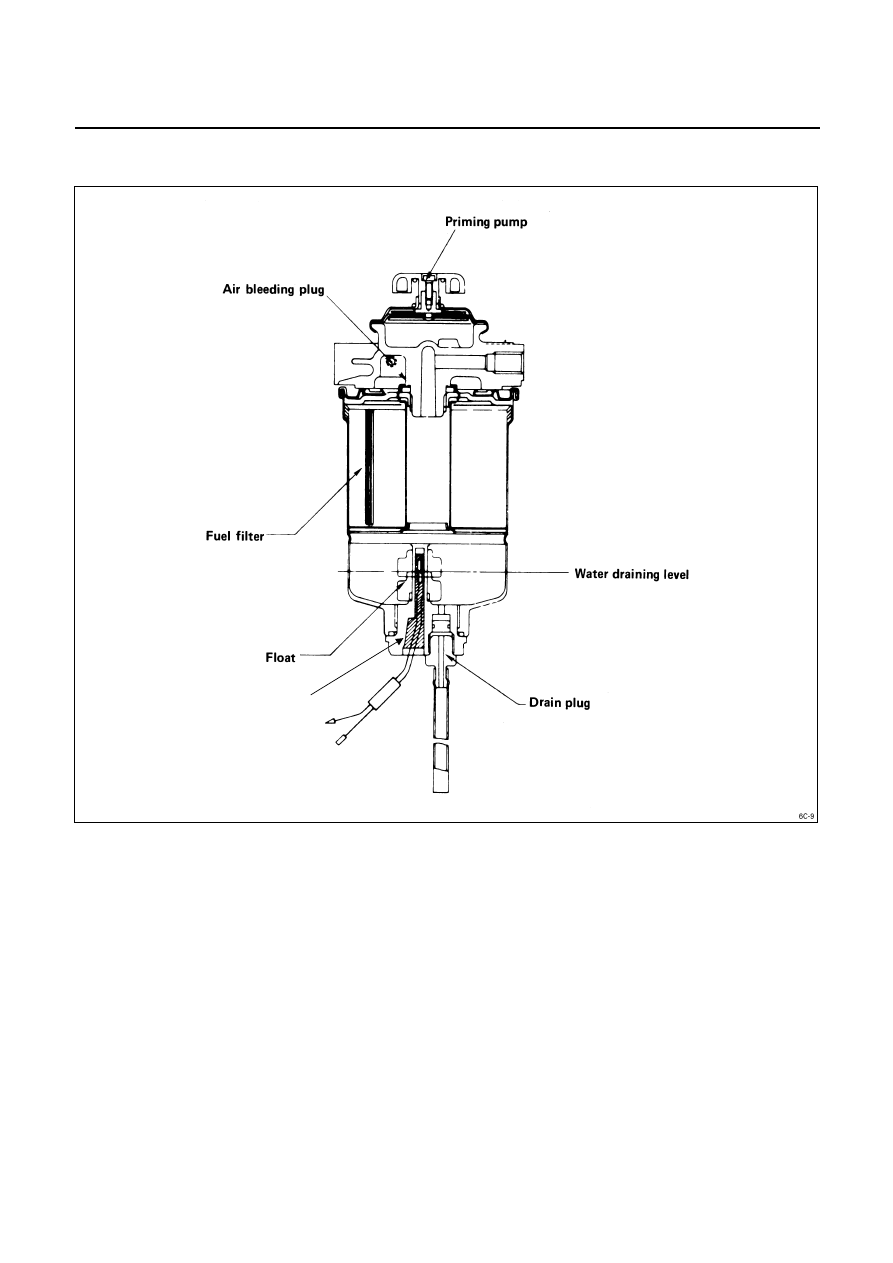
FUEL FILTER WITH BUILT-IN WATER SEPARATOR
A fuel filter with a built-in water separator is used along with the VE type injection pump.
As the inside of the injection pump is lubricated by the fuel which it is pumping, the fuel must be perfectly clean. The
fuel filter and the water separator remove water particles and other foreign material from the fuel before it reaches
the injection pump.
The water separator has an internal float. When the float reaches the specified level, a warning light comes on to
remind you to drain the water from the water separator.
A diaphragm type priming pump is installed at the top of the water separator. It is used during the water draining
and the air bleeding procedures.
Level Sensor
6C – 12 FUEL SYSTEM
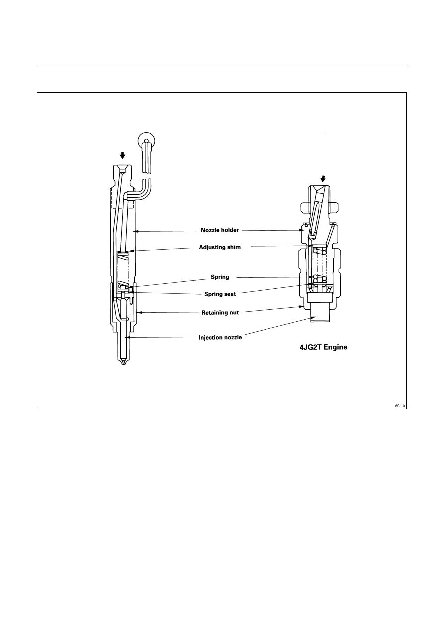
INJECTION NOZZLE
A hole (with 5 orifices) type injection nozzle is used for 4JA1T, 4JA1, 4JB1T Engine and a throttle type injection is
used for 4JG2T Engine. It consists of the nozzle body and the needle valve assembly.
The injection nozzle assembly sprays pressurized fuel from the injection pump into the combustion chamber
through the nozzle body injection orifice.

FUEL SYSTEM 6C – 13
INJECTION PUMP
REMOVAL AND INSTALLATION
Read this Section carefully before performing any removal and installation procedure. This Section gives you
important points as well as the order of operation. Be sure that you understand everything in this Section before you
begin.
BELT DRIVE MODEL (4JA1T, 4JG2T)
Removal Steps
1. Cooling
Fan
Drain the engine coolant.
The following parts must be removed before the cooling
fan can be removed.
Battery, Air cleaner duct, Radiator
Additionally, all piping, wiring, and hoses which will
interfere with the removal of the cooling fan must be
disconnected.
Refer to Section 6A, “REMOVAL AND INSTALLATON” of
this Manual for detailed information on part removal.
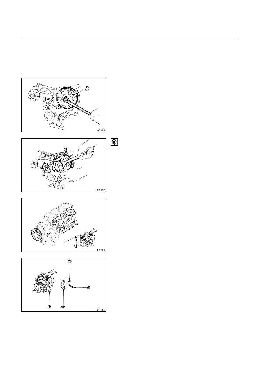
2. Crankshaft Damper Pulley
Turn the crankshaft to align the damper pulley mark with
the timing pointer.
This will bring the No. 1 piston to TDC on the compression
stroke.
3. Fuel Injection Pipe with Clip
1. Loosen the injection pipe sleeve nuts at the delivery
valve side
.
Do not apply excessive force to the injection pipes.
2. Loosen the injection pipe clips
.
3. Remove the injection pipes
.
Note:
Plug the delivery holder ports with the shipping caps
to prevent the entry of foreign material.
6C – 14 FUEL SYSTEM
4. Timing Case Cover Upper
5. Timing Case Cover Lower
6. Timing
Belt
1. Loosen the timing belt tensioner bolt and remove the
timing belt.
7. Injection Pump Timing Pulley
1. Install the stopper bolt
to the timing pulley to
prevent it from turning.
2. Use the timing pulley remover
to remove the
injection pump timing pulley.
Timing Pulley Puller: 5-8840-0086-0
3. Remove the stopper bolt.
8. Injection
Pump
1. Remove the three injection pump bracket nuts
at
the rear of the timing pulley housing.
2. Remove the injection pump rear bracket bolts
from
the injection pump bracket
.
3. Remove the injection pump rear bracket bolts
and
the bracket
from the cylinder body.
4. Pull the injection pump free toward the rear of the
engine.
Note:
Plug the injection pump delivery holder ports with the
shipping caps (or the equivalent) to prevent the entry
of foreign material.
Нет комментариевНе стесняйтесь поделиться с нами вашим ценным мнением.
Текст