Isuzu D-Max / Isuzu Rodeo (TFR/TFS). Manual — part 589
FUEL SYSTEM 6C – 15
Installation Steps
To install, follow the removal procedure in reverse order
and note the following point.
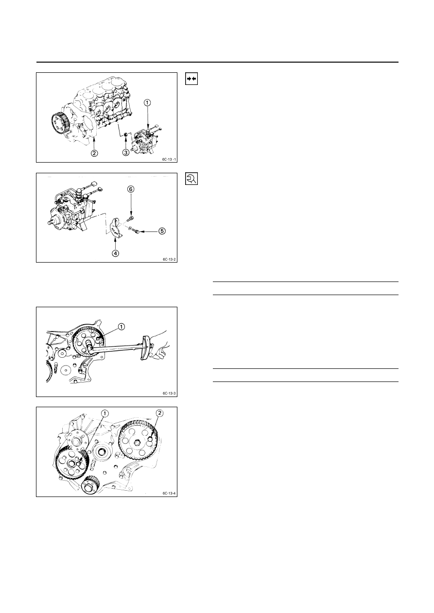
1. Injection
Pump
1) Install the injection pump
to the timing pulley
housing
.
2) Temporarily tighten the three injection pump nuts
.
The injection pump nuts will be finally tightened after
the injection pump rear bracket bolts.
3) Install the injection pump rear bracket
and the rear
bracket bolts
to the cylinder body.
4) Install the rear bracket bolts
to the injection pump
bracket.
Do not tighten the bolts.
The rear bracket bolts
and
will be finally tighten
tened to the specified torque after the injection pump
nuts.
5) Tighten the injection pump nuts to the specified
torque.
Injection Pump Nut and Bracket Bolt
Torque kg·m
(lb.ft/N·m)
1.5
± 0.5 (10.8 ± 3.6/14.7 ± 4.9)
2. Injection Pump Timing Pulley
1) Align the timing pulley with the pump shaft key.
2) Install the stopper bolt
to the timing pulley.
This will prevent the timing pulley from turning.
3) Tighten the timing pulley nut to the specified torque.
Injection Pump Timing Pulley Nut Torque kg·m (lb.ft/N·m)
6.5
± 0.5 (47.0 ± 3.6/63.7 ± 4.9)
3. Timing
Belt
4. Timing Belt Tensioner
5. Timing Belt Tension Adjusting Lever
1) Check that the stopper bolts are properly installed to
the camshaft timing pulley
and the injection pump
timing pulley
.
6C – 16 FUEL SYSTEM
2) Check that the timing pulley housing mark
and the
crankshaft timing pulley mark
are aligned.
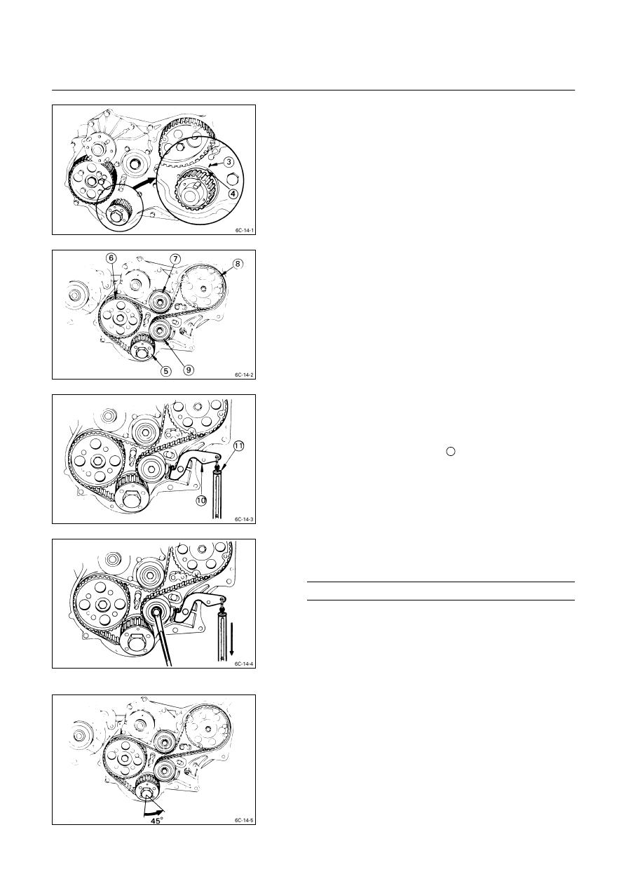
3) Install the timing belt to the crankshaft timing pulley
, the camshaft timing pulley
, the tensioner idler
, and the injection timing pulley
.
Follow the numerical order.
4) Install the timing belt tensioner
to the timing pulley
housing.
5) Temporarily tighten the tnesioner bolt.
The tensioner should move freely.
Note:
The timing belt is easily damaged. Be careful.
6) Set the tensioner adjusting lever
to the timing pulley
housing.
7) Remove the stopper bolts from the camshaft timing
pulley
and the injection pump timing pulley
.
8) Attach the spring balancer
11
.
9) Adjust timing belt tension by pulling straight down on
the spring balancer with the specified force.
Tension Adjusting Lever Force
kg (lb/N)
10 - 12 (22.1 – 26.5/98.1 – 117.7)
Note:
Timing belt tension must be adjusted.
Failure to adjust the timing belt tension will result in
timing belt damage.
10) Tighten the tension bolt.
11) Rotate the crankshaft 45 degrees counterclockwise.
Note:
Never rotate crankshaft clockwise when adjusting the
timing belt.

FUEL SYSTEM 6C – 17
12) Readjust the timing belt tension.
Refer to Step 9
This will remove any remaining timing belt slack.
13) Tighten the tensioner bolt to the specified torque.
Tensioner Bolt Torque
kg·m (lb.ft/N·m)
7.7
± 1.0 (55.7 ± 3.6/75.5 ± 9.8)
14) Tighten the tension adjusting lever nut
13
and bolt
14
.
Note:
If on-vehicle timing belt replacement is performed, the
crankshaft must not be allowed to turn.
If the crankshaft is allowed to turn, piston and valve
damage will result.

6C – 18 FUEL SYSTEM
GEAR DRIVE MODEL (4JA1, 4JB1T)
Removal Steps
1. Disconnect the battery ground cable.
2. Disconnect the air cleaner duct.
3. Disconnect the PCV hose.
4. Remove the head cover.
5. Remove the power steering V belt. (if so equipped)
6. Disconnect the accelerator cable and harness from
injection pump.
7. Remove the fuel pipes and injection pipes.
8. Remove the cover of timing gear case cover. (injection
pump side only)
9. Remove the timing hole cover.
10. For ease in reinstalling the injection pump, align the
timing “O” mark on the pump gear with the allow mark
on the timing gear case cover using the crank shaft
turning wrench.
11. Remove the six injection pump mounting bolts from
the timing gear case cover.
12. Remove the rear bracket bolts from the injection pump
bracket.
13. Pull the injection pump together with pump gear free
toward the rear of the engine.
Installation Steps
To install, follow the removal procedure in reverse order
and note the following point.
• Recheck the crankshaft to align the timing mark on the
crank pulley with the TDC mark.
Нет комментариевНе стесняйтесь поделиться с нами вашим ценным мнением.
Текст