Isuzu D-Max / Isuzu Rodeo (TFR/TFS). Manual — part 88

4JA1-TC/4JH1-TC ENGINE DRIVEABILITY AND EMISSIONS
6E–347
8
1. Using the Tech 2, display the ECT sensor and IAT
sensor value.
2. Check the displayed value.
Does the Tech 2 indicate correct temperature
depending on engine condition?
If a problem is found, repair as necessary.
Was the problem found?
—
Verify repair
Go to Step 9
9
1. Using the Tech 2, ignition “On” and engine “Run”.
2. Monitor the “Mass Air Flow” in the data display.
Does the Tech 2 indicate correct “Mass Air Flow”
depending on accelerator pedal operation?
—
Go to Step 14
Go to Step 10
10
Remove the MAF & IAT sensor assembly and check
for the following conditions.
• Objects blocking at the MAF sensor element.
If a problem is found, repair as necessary.
Was the problem found?
—
Verify repair
Go to Step 11
11
Check the MAF sensor harness for the following
conditions.
• Check for poor connector connection.
• Check for misrouted harness.
• Check for any accessory parts which may cause
electric interference.
If a problem is found, repair as necessary.
Was a problem found?
—
Verify repair
Go to Step 12
12
Substitute a known good MAF & IAT sensor assembly
and recheck.
Was the problem solved?
—
Go to Step 13
Go to Step 29
13
Replace the MAF & IAT sensor assembly.
Is the action complete?
—
Verify repair
—
14
1. Using the Tech 2, ignition “On” and engine “Off”.
2. Monitor the “Pedal/Throttle Position” and “Idle
Switch” in the data display.
Does the Tech 2 indicate correct “Pedal/Throttle
Position” from 0% to 100% and correct “Idle Switch”
status depending on accelerator pedal operation?
—
Go to Step 19
Go to Step 15
15
1. Using the Tech 2, ignition “On” and engine “Off”.
2. Monitor the “Pedal/Throttle Position” and “Idle
Switch” in the data display.
3. Adjust the accelerator cable or TPS within 0% to
100%.
Was the problem solved?
—
Verify repair
Go to Step 16
16
Check the TPS harness for the following conditions.
• Check for poor connector connection.
• Check for misrouted harness.
• Check for any accessory parts which may cause
electric interference.
If a problem is found, repair as necessary.
Was a problem found?
—
Verify repair
Go to Step 17
17
Substitute a known good TPS and recheck.
Was the problem solved?
—
Go to Step 18
Go to Step 29
18
Replace the TPS.
Is the action complete?
—
Verify repair
—
Step
Action
Value(s)
Yes
No

6E–348
4JA1-TC/4JH1-TC ENGINE DRIVEABILITY AND EMISSIONS
19
Remove the CKP sensor from the flywheel housing
and check for the following conditions.
• Objects sticking the CKP sensor.
• Objects sticking the CKP sensor pulser.
If a problem is found, repair as necessary.
Was the problem found?
—
Verify repair
Go to Step 20
20
Check the CKP sensor harness for the following
conditions.
• Check for poor connector connection.
• Check for misrouted harness.
• Check for any accessory parts which may cause
electric interference.
If a problem is found, repair as necessary.
Was a problem found?
—
Verify repair
Go to Step 21
21
Substitute a known good CKP sensor and recheck.
Was the problem solved?
—
Go to Step 22
Go to Step 23
22
Replace the CKP sensor.
Is the action complete?
—
Verify repair
—
23
1. Using the Tech 2 and ignition “On” and engine
“Run”.
2. Monitor the following parameters in the data
display.
• “Desired Injection Quantity” & “Injection Quantity”
• “Desired Injection Start” & “Actual Injection Start”
Are the large gap or unstable parameter displayed
between “Desired” and “Actual”?
—
Go to Step 25
Go to Step 24
24
Using the vacuum pump and check the EGR valve (if
equipped) operation for the following condition through
the small window.
• Restrict shaft movement. Check for objects sticking
the shaft, broken diaphragm or excessive carbon
deposit.
If a problem is found, repair as necessary.
Was a problem found?
—
Verify repair
Go to Step 25
Step
Action
Value(s)
Yes
No
When idling or part-throttle When accelerated
High
Desired
Low
Time
Actual
High
Low
Desired
Actual
Time
Vacuum Pump
Small Window
4JA1-TC/4JH1-TC ENGINE DRIVEABILITY AND EMISSIONS
6E–349
25
Visually/physically inspect for the following conditions.
• Restrict fuel supply system. Check for a pinched
fuel hose/pipe.
• Check for a condition that causes fuel waxing or
icing, such as the customer is using an incorrect
fuel type in winter season or water mixed with the
fuel.
If a problem is found, repair as necessary.
Was a problem found?
—
Verify repair
Go to Step 26
26
Replace the fuel filter.
Was the problem solved?
—
Verify repair
Go to Step 27
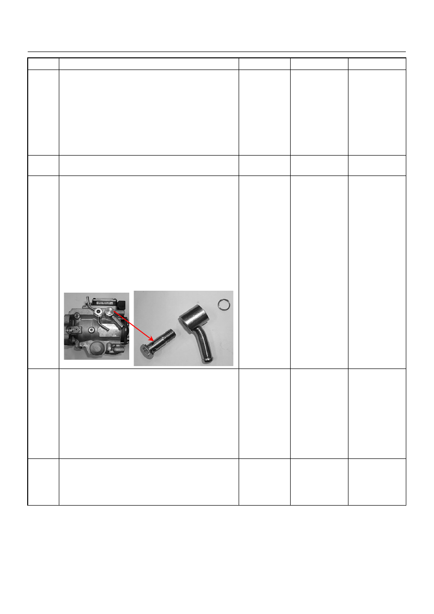
27
Remove the eye bolt with gauze filter from the
injection pump and check for the following conditions.
• Objects blocking at the gauze filter. Check for a
condition that causes contaminated fuel, such as
the customer is using an aftermarket fuel filter or
extended maintenance interval.
• Check for a condition that causes fuel waxing or
icing, such as the customer is using an incorrect
fuel type in winter season or water mixed with the
fuel.
If a problem is found, repair as necessary.
Was the problem found?
—
Replace the eye
bolt with gauze
filter and verify
repair
Go to Step 28
28
1. Review all diagnostic procedures within this table.
2. If all procedures have been completed and no
malfunctions have been found, review/inspect the
following:
• Visual/physical inspection
• Tech 2 data
• All electrical connections within a suspected circuit
and/or system
Was a problem found?
—
Verify repair
Go to Step 29
29
Is the ECM programmed with the latest software
release?
If not, download the latest software to the ECM using
the “SPS (Service Programming System)”.
Was the problem solved?
—
Verify repair
Go to Step 30
Step
Action
Value(s)
Yes
No

6E–350
4JA1-TC/4JH1-TC ENGINE DRIVEABILITY AND EMISSIONS
30
Substitute a known good ECM and recheck.
Was the problem solved?
IMPORTANT: The replacement ECM must be
programmed. Refer to section of the Service
Programming System (SPS) in this manual.
Following ECM programming, the immobiliser system
(if equipped) must be linked to the ECM. Refer to
section 11 “Immobiliser System-ECM replacement” for
the ECM/Immobiliser linking procedure.
—
Go to Step 31
Go to Step 32
31
Replace the ECM.
Is the action complete?
IMPORTANT: The replacement ECM must be
programmed. Refer to section of the Service
Programming System (SPS) in this manual.
Following ECM programming, the immobiliser system
(if equipped) must be linked to the ECM. Refer to
section 11 “Immobiliser System-ECM replacement” for
the ECM/Immobiliser linking procedure.
—
Verify repair
—
32
Replace the injection pump assembly.
Is the action complete?
—
Verify repair
—
Step
Action
Value(s)
Yes
No
Нет комментариевНе стесняйтесь поделиться с нами вашим ценным мнением.
Текст