Isuzu D-Max / Isuzu Rodeo (TFR/TFS). Manual — part 51

4JA1-TC/4JH1-TC ENGINE DRIVEABILITY AND EMISSIONS
6E–199
7
Check for poor/faulty connection at the ECM and other
connectors. If a poor/faulty connection is found, repair
the faulty terminal.
Was the problem found?
—
Verify repair
Go to Step 9
8
Remove the VSS from the housing case and visually
check.
Was the problem found?
—
Go to Step 10
Go to Step 9
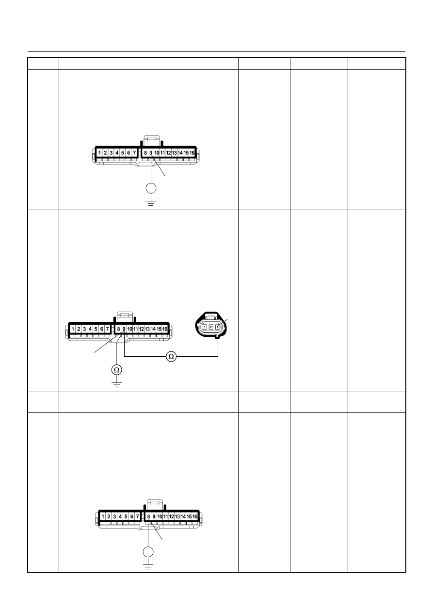
9
Using the DVM and check the VSS signal.
1. Ignition “On”, vehicle “Run (lift up)”.
2. Measure the VSS output voltage at sensor, meter
and ECM.
Does the tester indicate specified value?
If a oscilloscope is available, monitor the VSS signal at
each connector connection. Does the oscilloscope
indicate correct wave form?
Refer to
Diagnostic Aids
and Go to Step
16
Refer the table
10
Replace the VSS.
Is the action complete?
—
Verify repair
Step
Action
Value(s)
Yes
No
68
C-56
Measurement Position
Voltage (V)
(AC Range)
If No
Good
VSS terminal 3 & GND
Approximately 6.5
V at 20km/h
Go to
Step 10
Meter B23 connector 9 &
GND
Go to
Step 11
Meter B23 connector 8 &
GND
Go to
Step 13
ECM C56 connector 68 &
GND
Go to
Step 14
Vehicle Speed Sensor Reference Wave Form
0V
→
Measurement Scale: 10V/div
50ms/div
Measurement Condition: Vehicle Speed 20km/h
Measurement Terminal: At Engine Control Module
6E–200
4JA1-TC/4JH1-TC ENGINE DRIVEABILITY AND EMISSIONS
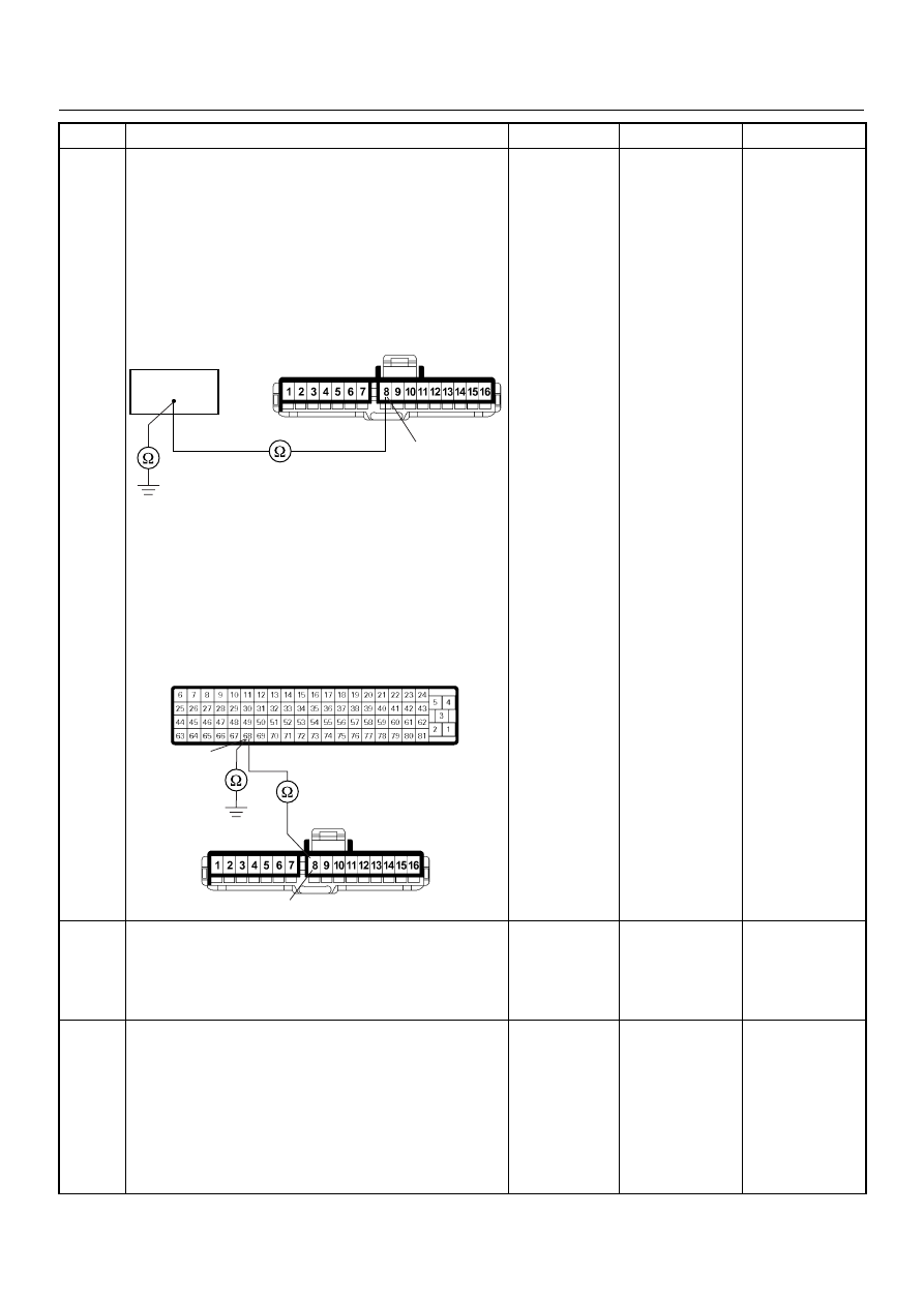
11
Using the DVM and check the VSS signal circuit.
1. Ignition “On”, engine “Off”.
2. Disconnect the meter connector.
3. Check the circuit for short to power supply circuit.
Was the DVM indicated specified value?
Less than 1V
Go to Step 12
Repair faulty
harness and
verify repair
12
Using the DVM and check the VSS signal circuit.
1. Ignition “Off”, engine “Off”.
2. Disconnect the VSS connector and meter
connector.
3. Check the circuit for open or short to ground
circuit.
If a open or short to ground circuit is found, repair the
faulty harness and verify repair.
Is the action complete?
—
Verify repair
—
13
Replace the speed meter.
Is the action complete?
—
Verify repair
—
14
Using the DVM and check the VSS signal circuit.
1. Ignition “Off”, engine “Off”.
2. Disconnect the meter connector and ECM
connector.
3. Ignition “On”.
4. Check the circuit for short to power supply circuit.
Was the DVM indicated specified value?
Less than 1V
Go to Step 15
Repair faulty
harness and
verify repair
Step
Action
Value(s)
Yes
No
9
V
B-23
3
9
E-44
B-23
8
V
B-23
4JA1-TC/4JH1-TC ENGINE DRIVEABILITY AND EMISSIONS
6E–201
15
Using the DVM and check the VSS signal circuit.
Breaker box is available:
1. Ignition “Off”, engine “Off”.
2. Install the breaker box as type A. (ECM
disconnected) Ref. Page 6E-81
3. Disconnect the meter connector.
4. Check the circuit for open or shot to ground circuit.
Was the problem found?
Breaker box is not available:
1. Ignition “Off”, engine “Off”.
2. Disconnect the meter connector and ECM
connector.
3. Check the circuit for open or short to ground
circuit.
Was the problem found?
—
Repair faulty
harness and
verify repair
Go to Step 16
16
Is the ECM programmed with the latest software
release?
If not, download the latest software to the ECM using
the “SPS (Service Programming System)”.
Was the problem solved?
—
Verify repair
Go to Step 17
17
Replace the ECM.
Is the action complete?
IMPORTANT: The replacement ECM must be
programmed. Refer to section of the Service
Programming System (SPS) in this manual.
Following ECM programming, the immobiliser system
(if equipped) must be linked to the ECM. Refer to
section 11 “Immobiliser System-ECM replacement” for
the ECM/Immobiliser linking procedure.
—
Verify repair
—
Step
Action
Value(s)
Yes
No
8
B-23
68
68
8
B-23
C-56
6E–202
4JA1-TC/4JH1-TC ENGINE DRIVEABILITY AND EMISSIONS
DIAGNOSTIC TROUBLE CODE (DTC) P0560 (SYMPTOM CODE 1)
(FLASH CODE 35) SYSTEM VOLTAGE TOO HIGH
DIAGNOSTIC TROUBLE CODE (DTC) P0560 (SYMPTOM CODE 2)
(FLASH CODE 35) SYSTEM VOLTAGE TOO LOW
DIAGNOSTIC TROUBLE CODE (DTC) P0560 (SYMPTOM CODE A)
(FLASH CODE 35) SYSTEM VOLTAGE MALFUNCTION (PSG)
Condition for setting the DTC and action taken when the DTC sets
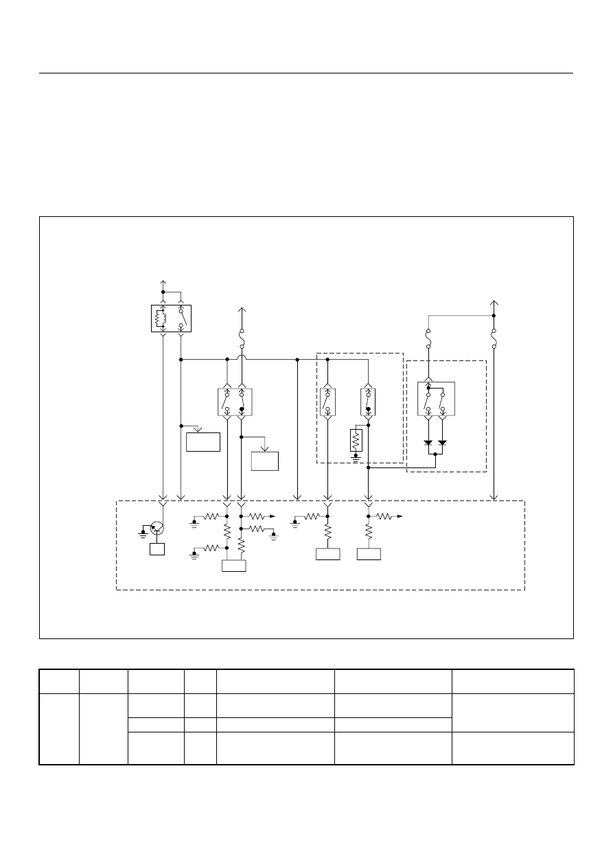
Circuit Description
The ECM and PSG monitors the system voltage on the
ignition feed terminal to the ECM or PSG. The system
voltage to the ECM excessively high or low, DTC P0560
(Symptom Code 1) or P0560 (Symptom Code 2) will be
stored. The system voltage to the PSG excessively high
Flash
Code
Code
Symptom
Code
MIL
DTC Name
DTC Setting Condition
Fail-Safe (Back Up)
35
P0560
1
OFF
System Voltage Too High
System voltage is more than
20V.
ECM uses 9V conditions as
substitute.
2
OFF
System Voltage Too Low
System voltage is below 7V.
A
OFF
System Voltage Malfunction
(PSG)
System voltage of PSG
(pump control unit) is below
4.5V or more than 27V.
PSG uses default voltage as
substitute.
Battery
Voltage
Battery
Voltage
ECM
Main Relay
Stop
Light
10A
Injection
Pump
Stop
Lamp
IC
IC
CPU
0.5
BLU/
BLK
58
2.0
BLU/
RED
0.5
BLU/
RED
3
0.5
WHT/
BLK
65
0.85
RED
0.85
RED
0.85
GRN
30
0.5
BLU/
RED
63
0.5
YEL
31
0.5
RED/
BLK
0.5
BLU/
RED
0.5
BLU/
RED
0.85
WHT
0.5
WHT/
RED
0.5
RED/
GRN
Clutch
SW
Resister
Neutral
SW
87
0.5
BLU/
YEL
39
Brake
SW
M/T
A/T
Inhibitor
SW
Ignition
SW
Back,
Turn
15A
Engine
15A
µP
N
P
Engine
Control
Module
(ECM)
Batt
Batt
Нет комментариевНе стесняйтесь поделиться с нами вашим ценным мнением.
Текст