Isuzu D-Max / Isuzu Rodeo (TFR/TFS). Manual — part 49
4JA1-TC/4JH1-TC ENGINE DRIVEABILITY AND EMISSIONS
6E–191
3
1. Using the Tech 2, ignition “On” and engine “Off”.
2. Select “F1: Clear DTC Information” in “F0:
Diagnostic Trouble Codes” with the Tech 2 and
clear the DTC information.
3. Operate the vehicle and monitor the “F0: Read
DTC Infor As Stored By ECU” in the “F0:
Diagnostic Trouble Codes”.
Was the DTC P0500 (Symptom Code 1) stored in this
ignition cycle?
—
Go to Step 4
Refer to
Diagnostic Aids
and Go to Step
4
4
Perform test drive and check the speed meter.
Does the speed meter indicate correct vehicle speed.
—
Go to Step 5
Go to Step 6
5
Perform test drive and use the Tech 2.
Monitor the “Vehicle Speed” in the data display.
Does the Tech 2 indicate correct vehicle speed as
same as the speed meter indication in the instrument
panel?
—
Go to Step 14
Go to Step 7
6
Remove the VSS from the housing case and visually
check.
Was the problem found?
—
Go to Step 8
Go to Step 7
7
Using the DVM and check the VSS signal.
1. Ignition “On”, vehicle “Run (lift up)”.
2. Measure the VSS output voltage at sensor, meter
and ECM.
Does the tester indicate specified value?
If a oscilloscope is available, monitor the VSS signal at
each connector connection. Does the oscilloscope
indicate correct wave form?
Refer to
Diagnostic Aids
and Go to Step
14
Refer the table
Step
Action
Value(s)
Yes
No
Measurement Position
Voltage (V)
(AC Range)
If No
Good
VSS terminal 3 & GND
Approximately 6.5
V at 20km/h
Go to
Step 8
Meter B23 connector 9 &
GND
Go to
Step 9
Meter B23 connector 8 &
GND
Go to
Step 11
ECM C56 connector 68 &
GND
Go to
Step 12
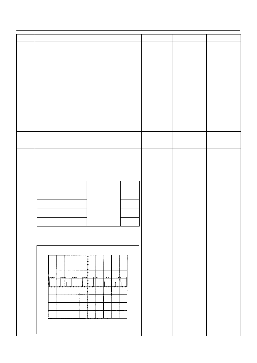
Vehicle Speed Sensor Reference Wave Form
0V
→
Measurement Scale: 10V/div
50ms/div
Measurement Condition: Vehicle Speed 20km/h
Measurement Terminal: At Engine Control Module
6E–192
4JA1-TC/4JH1-TC ENGINE DRIVEABILITY AND EMISSIONS
8
Replace the VSS.
Is the action complete?
—
Verify repair
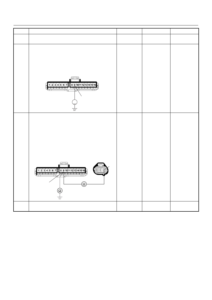
9
Using the DVM and check the VSS signal circuit.
1. Ignition “On”, engine “Off”.
2. Disconnect the meter connector.
3. Check the circuit for short to power supply circuit.
Was the DVM indicated specified value?
Less than 1V
Go to Step 10
Repair faulty
harness and
verify repair
10
Using the DVM and check the VSS signal circuit.
1. Ignition “Off”, engine “Off”.
2. Disconnect the VSS connector and meter
connector.
3. Check the circuit for open or short to ground
circuit.
If a open or short to ground circuit is found, repair the
faulty harness and verify repair.
Is the action complete?
—
Verify repair
—
11
Replace the speed meter.
Is the action complete?
—
Verify repair
—
Step
Action
Value(s)
Yes
No
9
V
B-23
3
9
E-44
B-23
4JA1-TC/4JH1-TC ENGINE DRIVEABILITY AND EMISSIONS
6E–193
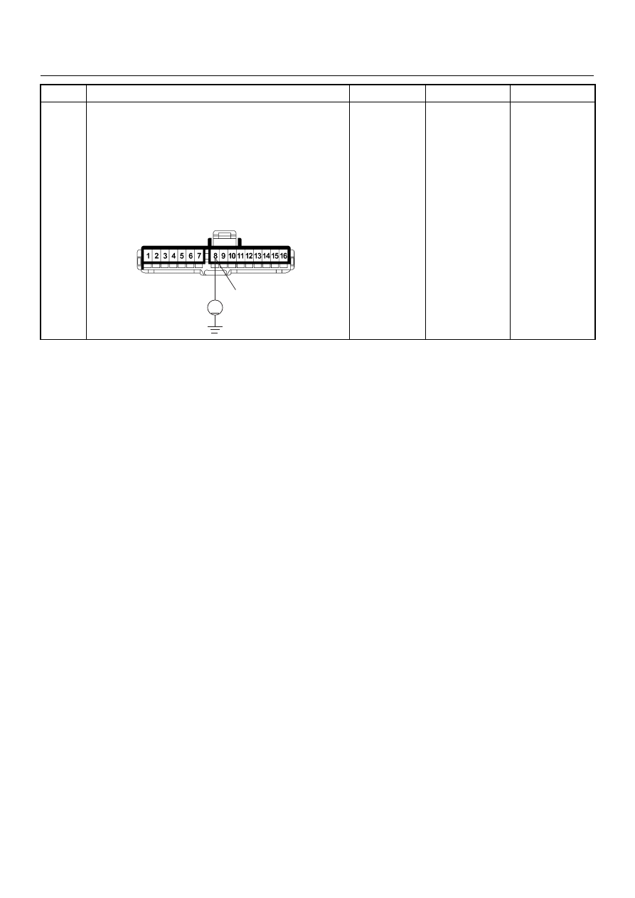
12
Using the DVM and check the VSS signal circuit.
1. Ignition “Off”, engine “Off”.
2. Disconnect the meter connector and ECM
connector.
3. Ignition “On”.
4. Check the circuit for short to power supply circuit.
Was the DVM indicated specified value?
Less than 1V
Go to Step 13
Repair faulty
harness and
verify repair
Step
Action
Value(s)
Yes
No
8
V
B-23
6E–194
4JA1-TC/4JH1-TC ENGINE DRIVEABILITY AND EMISSIONS
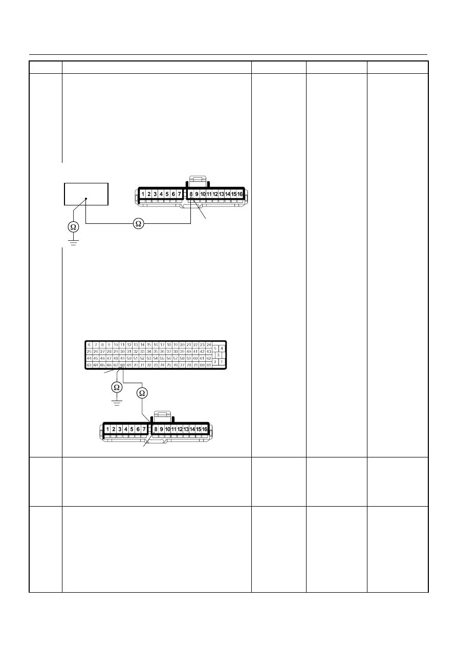
13
Using the DVM and check the VSS signal circuit.
Breaker box is available:
1. Ignition “Off”, engine “Off”.
2. Install the breaker box as type A. (ECM
disconnected) Ref. Page 6E-81
3. Disconnect the meter connector.
4. Check the circuit for open or shot to ground circuit.
Was the problem found?
Breaker box is not available:
1. Ignition “Off”, engine “Off”.
2. Disconnect the meter connector and ECM
connector.
3. Check the circuit for open or short to ground
circuit.
Was the problem found?
—
Repair faulty
harness and
verify repair
Go to Step 14
14
Is the ECM programmed with the latest software
release?
If not, download the latest software to the ECM using
the “SPS (Service Programming System)”.
Was the problem solved?
—
Verify repair
Go to Step 15
15
Replace the ECM.
Is the action complete?
IMPORTANT: The replacement ECM must be
programmed. Refer to section of the Service
Programming System (SPS) in this manual.
Following ECM programming, the immobiliser system
(if equipped) must be linked to the ECM. Refer to
section 11 “Immobiliser System-ECM replacement” for
the ECM/Immobiliser linking procedure.
—
Verify repair
—
Step
Action
Value(s)
Yes
No
8
B-23
68
68
8
B-23
C-56
Нет комментариевНе стесняйтесь поделиться с нами вашим ценным мнением.
Текст